Display lines:
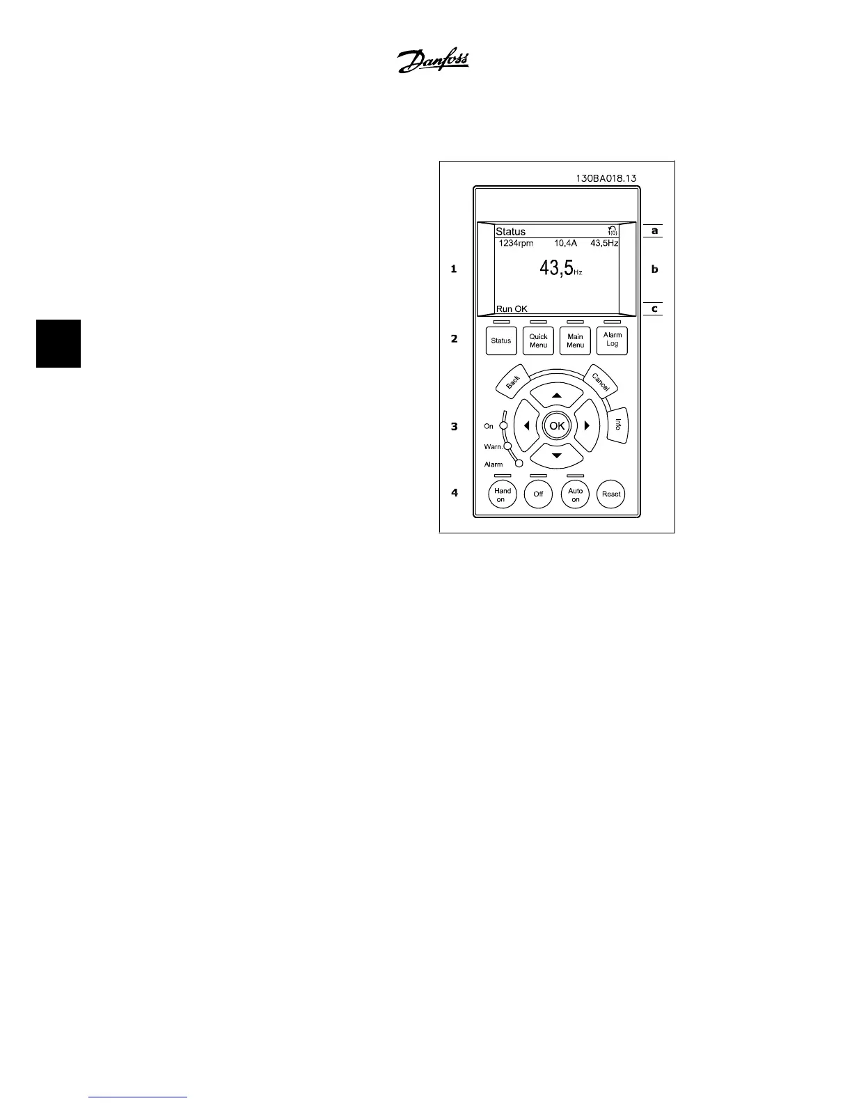
a. Status line: Status messages dis-
playing icons and graphics.
b. Line 1-2: Operator data lines dis-
playing data and variables defined or
chosen by the user. By pressing the
[Status] key, up to one extra line can
be added.
c. Status line: Status messages dis-
playing text.
The display is divided into 3 sections:
Top section(a) shows the status when in status mode, or up to 2 variables when not in status
mode and in the case of an alarm/warning.
The number of the active set-up (selected as the active set-up in par. 0-10) is shown. When
programming in another set-up than the active set-up, the number of the set-up being program-
med appears to the right in brackets.
The middle section (b) shows up to 5 variables with related units, regardless of status. In case
of an alarm/warning, the warning is shown instead of the variables.
It is possible to toggle between three status read-out displays by pressing the [Status] key.
Operating variables with different formatting are shown in each status screen - see below.
Several values or measurements can be linked to each of the displayed operating variables. The
values/measurements to be displayed can be defined via par. 0-20, 0-21, 0-22, 0-23, and 0-24,
which can be accessed via [QUICK MENU], "Q3 Function Set-ups", "Q3-1 General Settings",
"Q3-11 Display Settings".
Each value/measurement readout parameter selected in par. 0-20 to par. 0-24 has its own scale
and number of digits after a possible decimal point. Larger numeric values are displayed with few
digits after the decimal point.
Ex.: Current readout
5. How to operate the adjustable frequency
drive
VLT
®
HVAC Drive Instruction Manual
50
MG.11.A4.22 - VLT
®
is a registered Danfoss trademark
5

 Loading...


