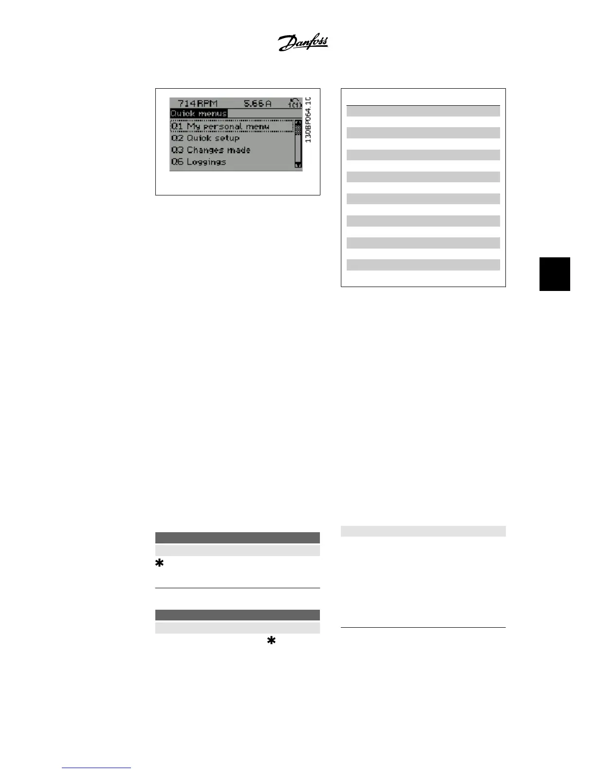
Illustration 6.1: Quick menu view.
Par. Designation [Units]
0-01 Language
1-20 Motor Power [kW]
1-21 Motor Power* [HP]
1-22 Motor Voltage [V]
1-23 Motor Frequency [Hz]
1-24 Motor Current [A]
1-25 Motor Nominal Speed [RPM]
3-41 Ramp 1 Ramp-up Time [s]
3-42 Ramp 1 Ramp-down Time [s]
4-11 Motor Speed Low Limit [RPM]
4-12 Motor Speed Low Limit* [Hz]
4-13 Motor Speed High Limit [RPM]
4-14 Motor Speed High Limit* [Hz]
3-11 Jog Speed* [Hz]
5-12 Terminal 27 Digital Input
5-40 Function Relay
Table 6.3: Quick Set-up parameters
*The display showing depends on choices made in parameter 0-02 and 0-03. The default setting
of parameters 0-02 and 0-03 depends on which region of the world the adjustable frequency drive
is supplied to, but it can be re-programmed as required.
If
No Operation
is selected in terminal 27, no connection to +24 V on terminal 27 is necessary to
enable start.
If
Coast Inverse
(factory default value) is selected in Terminal 27, a connection to +24V is nec-
essary to enable start.
Select
Changes made
to get information about:
• the last 10 changes. Use the up/down navigation keys to scroll between the last 10
changed parameters.
• the changes made since default setting.
Select
Loggings
to get information about the display line readouts. The information is shown in
graphs.
Only display parameters selected in par. 0-20 and par. 0-24 can be viewed. It is possible to store
up to 120 samples in the memory for later reference.
0-01 Language
Value:
English UK (English) [0]
1-20 Motor power parameter
Value:
0.09 - 500 kW
Size related
Function:
Enter the nominal motor power (in kW) ac-
cording to the motor nameplate data. The
default value corresponds to the nominal rat-
ed output of the unit.
This parameter cannot be adjusted while the
motor is running.
VLT
®
HVAC Drive Instruction Manual
6. How to program the adjustable frequency
drive
MG.11.A4.22 - VLT
®
is a registered Danfoss trademark
65
6

 Loading...


