5.2 Danfoss FC Control Profile
5.2.1 Danfoss FC Control Profile
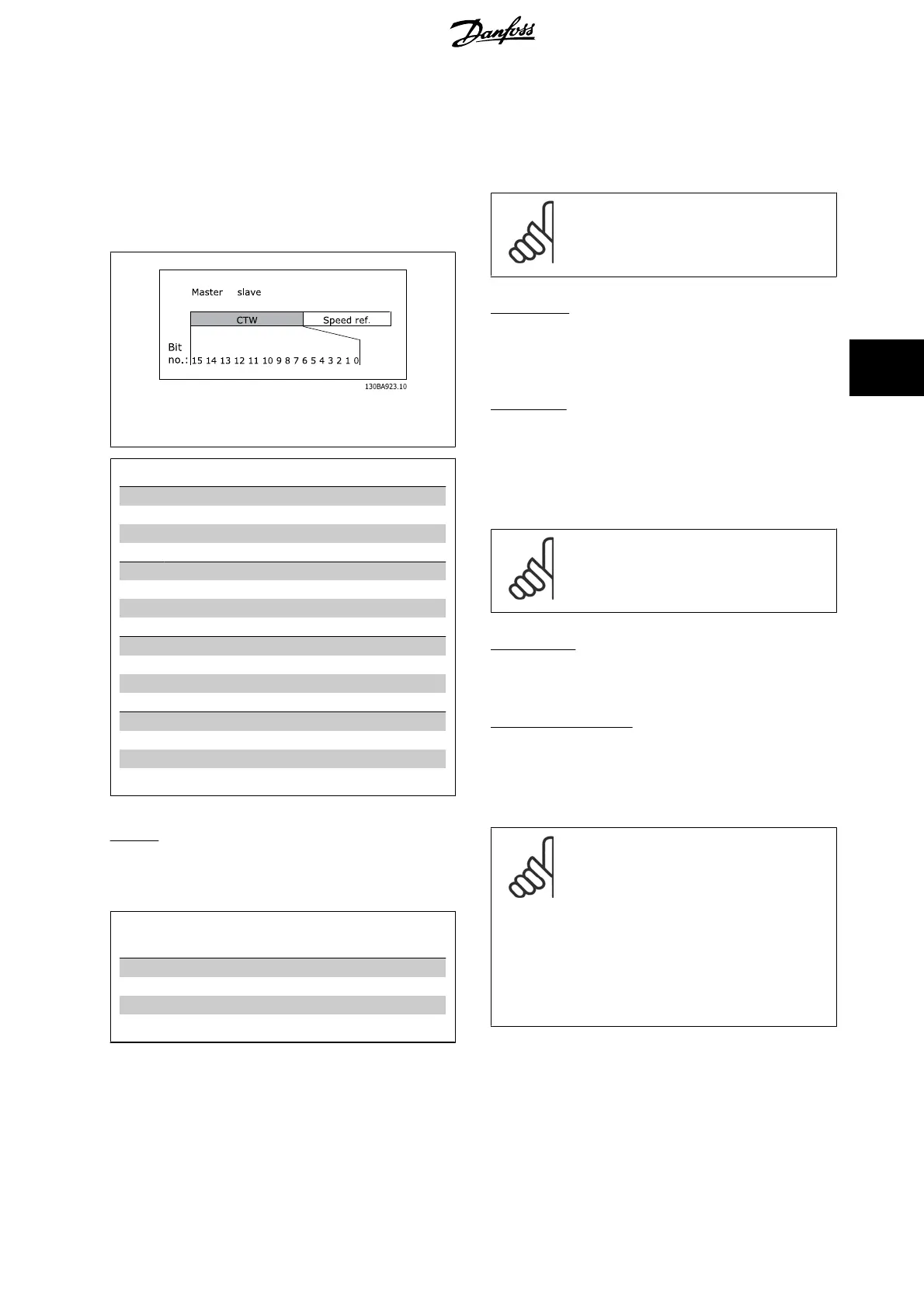
Control Word according to FC ProfileDrive Profile. Instances 100, 101,
103/150, 151, 153
→
Illustration 5.1: (par.8-10
Control Word Profile
= FC profile)
Bit Bit value = 0 Bit value = 1
00 Reference value External selection LSB
01 Reference value External selection MSB
02 DC brake Ramp
03
Coasting No coasting
04 Quick stop Ramp
05 Hold output frequency Use ramp
06 Ramp stop Start
07
No function Reset
08 No function Jog
09 Ramp 1 Ramp 2
10 Data invalid Data valid
11
No function Relay 01 active
12 No function Relay 04 active
13 Parameter set-up Selection LSB
14 Parameter set-up Selection MSB
15 No function Reverse
Explanation of Control Bits
Bits 00/01
Bits 00 and 01 are used to choose between the four reference values,
which are pre-programmed in par. 3-10
Preset Reference
according to
the following table:
Programmed
ref. value
Parameter Bit 01 Bit 00
1 3-10 [0] 0 0
2 3-10 [1] 0 1
3 3-10 [2] 1 0
4 3-10 [3] 1 1
NB!
In par. 8-56
Preset Reference Select
select a selection
is made to define how Bit 00/01 gates with the corre-
sponding function on the digital inputs.
Bit 02, DC brake:
Bit 02 = ‘0’ leads to DC braking and stop. Braking current and duration
are set in par. 2-01
DC Brake Current
and par. 2-02
DC Braking Time
. Bit
02 = ‘1’ leads to ramping, par. 3-41
Ramp 1 Ramp up Time
Bit 03, Coasting:
Bit 03 = ‘0’ causes the frequency converter to immediately "let go" of the
motor (the output transistors are "shut off"), so that it coasts to a stand-
still.
Bit 03 = ‘1’ enables the frequency converter to start the motor if the other
starting conditions have been fulfilled.
NB!
In par. 8-50
Coasting Select
a selection is made to de-
fine how Bit 03 gates with the corresponding function
on a digital input.
Bit 04, Quick stop:
Bit 04 = ‘0’ causes a stop, in which the motor speed is ramped down to
stop via par. 3-81
Quick Stop Ramp Time
.
Bit 05, Hold output frequency:
Bit 05 = ‘0’ causes the present output frequency (in Hz) to freeze. The
frozen output frequency can then be changed only by means of the digital
inputs (par. 5-10
Terminal 18 Digital Input
to par. 5-15
Terminal 33 Digital
Input
) programmed to
Speed up
and
Speed down
.
NB!
If Freeze output is active, the frequency converter can
only be stopped by the following:
• Bit 03 Coasting stop
•Bit 02 DC braking
• Digital input (par. 5-10
Terminal 18 Digital
Input
to par. 5-15
Terminal 33 Digital Input
)
programmed to
DC braking
,
Coasting stop
or
Reset and coasting stop
MCA 121 EtherNet/IP 5 How to Control
MG.90.J2.02 - VLT
®
is a registered Danfoss trademark
25
5

 Loading...