Explanation of the Bits:
Bit 0, Run Fwd:
Bit 0 = "0" means that the VLT frequency converter has a stop command.
Bit 0 = "1" leads to a start command and the VLT frequency converter
will start to run the motor clockwise.
Bit 1, Run Rev:
Bit 1 = "0" leads to a stop of the motor. Bit 1 = "1" leads to a start of the
motor.
Bit 2, Fault Reset:
Bit 2 = "0" means that there is no trip reset. Bit 2 = "1" means that a trip
is reset.
Bit 3, No function:
Bit 3 has no function.
Bit 4, No function:
Bit 4 has no function.
Bit 5, Net Control:
Bit 5 = "0" means that the drive is controlled from the standard inputs.
Bit 5 = "1" means that EIP controls the drive.
NB!
Please note that changes will affect parameters 8-50
to 8-56.
Bit 6, Net Reference:
Bit 6 = "0" Reference is from the standard inputs. Bit 6 = "1" Reference
is from EIP.
NB!
Please note that changes will affect par. 3-15
Refer-
ence Resource 1
to par. 3-17
Reference Resource 3
.
For the Speed reference, see section
Bus speed refer-
ence value under Instances 20/70 and 21/71
.
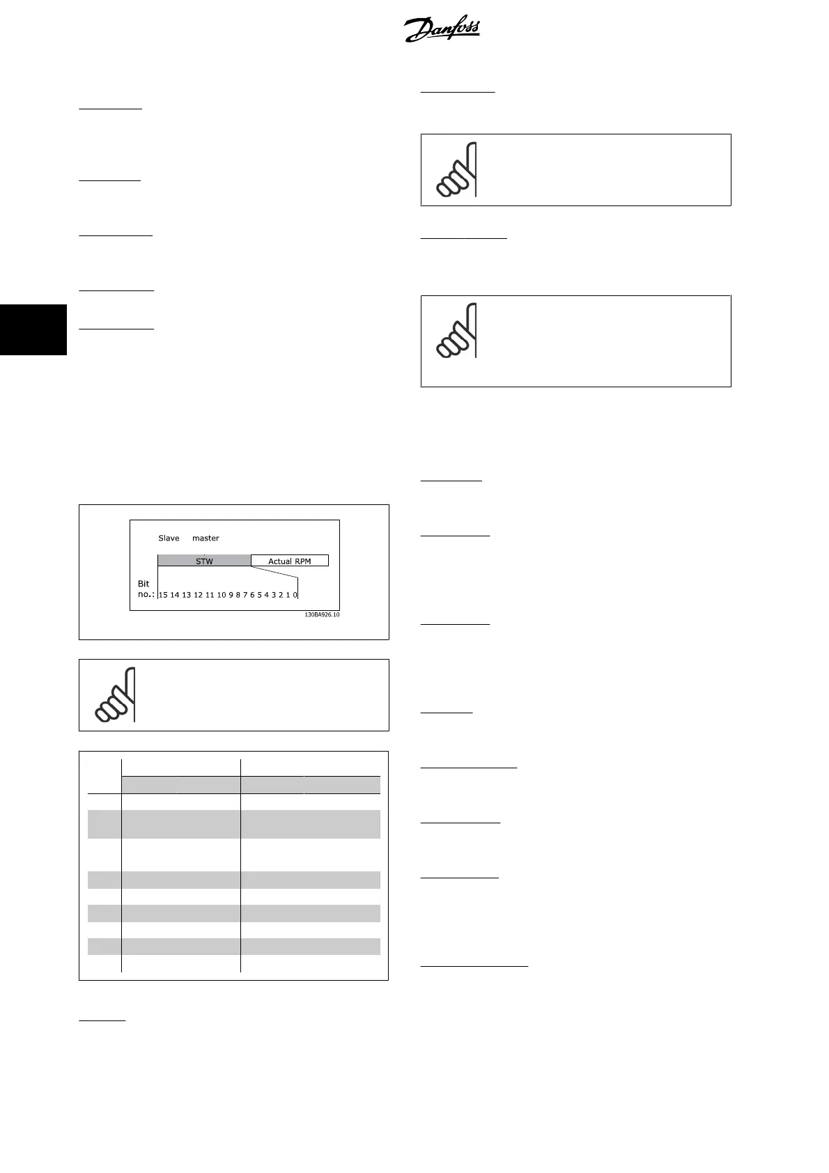
5.3.2 Status Word under Instances 20/70 and 21/71
The status word in Instances 70 and 71 is defined as follows:
→
NB!
Bits 00 and 02 in Instance 70 are identical with bits 00
and 02 in the more extensive Instance 71.
Bit
Instance 70 Instance 71
Bit = 0 Bit =1 Bit = 0 Bit =1
00 No Fault Fault No Fault Fault
01 - - - Warning
02
- Running 1
Fwd
- Running 1 Fwd
03 - - - Running 2 Rev.
04
-- -Ready
05 - - - Ctrl from Net
06
-- -Ref. from Net
07 - - - At ref.
08-15
-- State Attribute
Explanation of the Bits:
Bit 0, Fault:
Bit 0 = "0" means that there is no fault in the frequency converter. Bit 0
= "1" means that there is a fault in the frequency converter.
Bit 1, Warning:
Bit 0 = "0" means that there is no unusual situation. Bit 0 = "1" means
that an abnormal condition has occurred.
Bit 2, Running 1:
Bit 2 = "0" means that the drive is not in one of these states or that Run
1 is not set. Bit 2 = "1" means that the drive state attribute is enabled or
stopping, or that Fault-Stop and bit 0 (Run 1) of the control word are set
at the same time.
Bit 3, Running 2:
Bit 3 = "0" means that the drive is in neither of these states or that Run
2 is not set. Bit 3 = "1" means that the drive state attribute is enabled or
stopping, or that fault-stop and bit 0 (Run 2) of the control word are set
at the same time.
Bit 4, Ready:
Bit 4 = "0" means that the state attribute is in another state. Bit 4 = "1"
means that the state attribute is ready, enabled or stopping.
Bit 5, Control from net:
Bit 5 = "0" means that the drive is controlled from the standard inputs.
Bit 5 = "1" means that EIP has control (start, stop, reverse) of the drive.
Bit 6, Ref from net:
Bit 6 = "0" means that the reference comes from inputs to the drive. Bit
6 = "1" means that the reference comes from EIP.
Bit 7, At reference:
Bit 7 = "0" means that the motor is running, but that the present speed
is different from the preset speed reference, i.e. the speed is being ram-
ped up/down during start/stop. Bit 7 = "1" means that the drive and
reference speeds are equal.
Bit 8 - 15, State attribute:
(Instance 71 only) Represents the state attribute of the drive, as indicated
in the following table:
5 How to Control MCA 121 EtherNet/IP
28
MG.90.J2.02 - VLT
®
is a registered Danfoss trademark
5

 Loading...