Explanation of the Status Bits
Bit 00, Control ready:
Bit 00 = ‘0’ means that the frequency converter has tripped. Bit 00 = ‘1’
means that the frequency converter controls are ready, but that the pow-
er component is not necessarily receiving any power supply (in the event
of external 24 V supply to controls).
Bit 01, Drive ready:
Bit 01 = ‘1’. The frequency converter is ready for operation.
Bit 02, Coasting stop:
Bit 02 = ‘0’. The frequency converter has released the motor. Bit 02 =
‘1’. The frequency converter can start the motor when a start command
is given.
Bit 03, No error/Trip:
Bit 03 = ‘0’ means that the frequency converter is not in fault mode. Bit
03 = ‘1’ means that the frequency converter is tripped, and that a reset
signal is required to re-establish operation.
Bit 04, No error/Error (no trip):
Bit 04 = ‘0’ means that the frequency converter is not in fault mode. Bit
04 = ‘1’ means that there is a frequency converter error but no trip.
Bit 05, Reserved:
Bit 05 is not used in the status word.
Bit 06, No error / Trip lock:
Bit 06 = ‘0’ means that the frequency converter is not in fault mode. Bit
06 = ‘1’ means that the frequency converter is tripped, and locked.
Bit 07, No warning/Warning:
Bit 07 = ‘0’ means that there are no warnings. Bit 07 = ‘1’ means that a
warning has occurred.
Bit 08, Speed≠ reference/Speed = reference:
Bit 08 = ‘0’ means that the motor is running, but that the present speed
is different from the preset speed reference. For example, this might oc-
cur while the speed is being ramped up/down during start/stop. Bit 08 =
‘1’ means that the present motor speed matches the preset speed refer-
ence.
Bit 09, Local operation/Bus control:
Bit 09 = ‘0’ means that [STOP/RESET] is activated on the control unit, or
that Local control in par. 3-13
Reference Site
is selected. It is not possible
to control the frequency converter via serial communication. Bit 09 = ‘1’
means that it is possible to control the frequency converter via the field-
bus/ serial communication.
Bit 10, Out of frequency limit:
Bit 10 = ‘0’, if the output frequency has reached the value in
par. 4-11
Motor Speed Low Limit [RPM]
or par. 4-13
Motor Speed High
Limit [RPM]
. Bit 10 = ‘1’ means that the output frequency is within the
defined limits.
Bit 11, No operation/In operation:
Bit 11 = ‘0’ means that the motor is not running. Bit 11 = ‘1’ means that
the frequency converter has a start signal or that the output frequency is
greater than 0 Hz.
Bit 12, Drive OK/Stopped, auto start:
Bit 12 = ‘0’ means that there is no temporary over temperature on the
inverter. Bit 12 = ‘1’ means that the inverter has stopped because of over
temperature, but that the unit has not tripped and will resume operation
once the over temperature stops.
Bit 13, Voltage OK/Voltage exceeded:
Bit 13 = ‘0’ means that there are no voltage warnings. Bit 13 = ‘1’ means
that the DC voltage in the frequency converter’s intermediate circuit is
too low or too high.
Bit 14, Torque OK/Torque limit exceeded:
Bit 14 = ‘0’ means that the motor current is lower than the torque limit
selected in par. 4-16 and 4-17 Torque limit. Bit 14 = ‘1’ means that the
torque limit in par. 4-16 and 4-17 Torque limit has been exceeded. The
nominal torque can be read in par. 16-16
Torque [Nm]
.
Bit 15, Thermal OK/limit exceeded:
Bit 15 = ‘0’ means that the timers for both motor thermal protection and
VLT thermal protection, have not exceeded 100%. Bit 15 = ‘1’ means that
one of the limits has exceeded 100%.
5.3 ODVA Control Profile
5.3.1 Control Word under Instances 20/70 and 21/71
Set par.8-10
Control Word Profile
to ODVA.
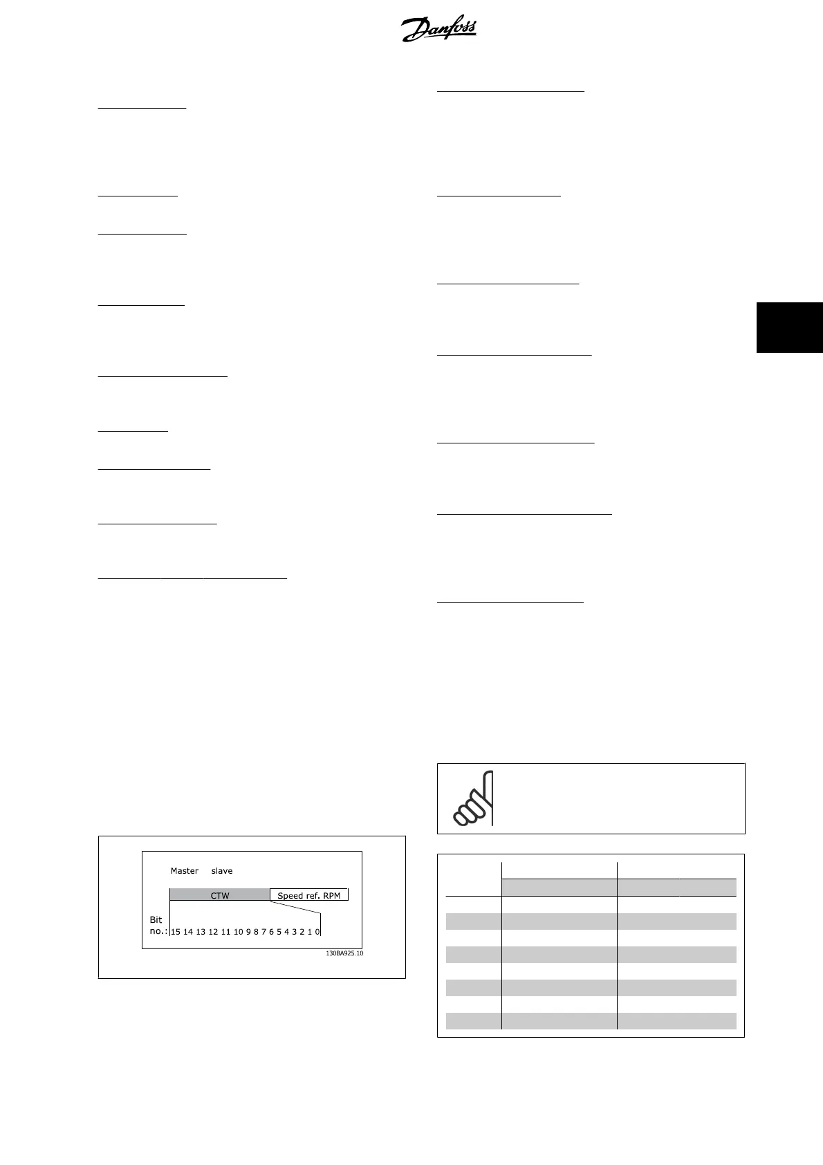
The control word in Instances 20 and 21 is defined as follows:
→
NB!
Bits 00 and 02 in Instance 20 are identical with bits 00
and 02 in the more extensive Instance 21.
Bit
Instance 20 Instance 21
Bit = 0 Bit =1 Bit = 0 Bit =1
00 Stop Run Fwd Stop Run Fwd
01 - - Stop Run Rev
02
No function Fault reset No function Fault reset
03 - - - -
04
----
05 - - - Net Ctrl
06
--- Net Ref
07-15 - - - -
MCA 121 EtherNet/IP 5 How to Control
MG.90.J2.02 - VLT
®
is a registered Danfoss trademark
27
5

 Loading...