1-55 U/f Characteristic - U
Range: Function:
Size related* [0 - 500
V]
Enter voltage at each frequency point
to manually form a U/f characteristic
matching motor. Frequency points are
dened in parameter 1-56 U/f Charac-
teristic - F.
1-56 U/f Characteristic - F
Range: Function:
Size
related*
[ 0 -
400.0
Hz]
Enter frequency points to form a U/f charac-
teristic matching motor. Voltage at each point
is dened in parameter 1-55 U/f Characteristic
- U.
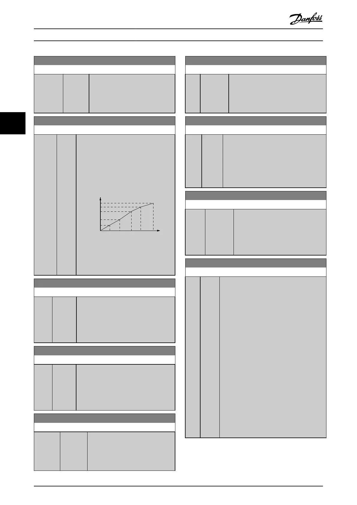
Make a U/f characteristic based on 6
denable voltages and frequencies, see
Illustration 4.2.
Motor Voltage
Par 1-55 [x]
Output Frequency
Par 1-56 [x]
1-55[5]
1-55[4]
1-55[3]
1-55[2]
1-55[1]
1-55[0]
1-56
[0]
1-56
[1]
1-56
[2]
1-56
[3]
1-56
[4]
1-56
[5]
130BA166.10
Illustration 4.2 Example of U/f Charac-
teristic
1-60 Low Speed Load Compensation
Range: Function:
100 %* [0 -
300 %]
Enter the low-speed voltage compensation
value in percent. This parameter is used for
optimizing the low-speed load performance.
This parameter is only active if
parameter 1-10 Motor Construction = [0]
Asynchron.
1-61 High Speed Load Compensation
Range: Function:
100 %* [0 -
300 %]
Enter the high-speed load voltage compen-
sation value in percent. This parameter is
used for optimizing the high-speed load
performance. This parameter is only active if
parameter 1-10 Motor Construction = [0]
Asynchron.
1-62 Slip Compensation
Range: Function:
Size
related*
[ -400 -
399.0 %]
Enter the % value for slip compensation
to compensate for tolerance in the
value of n
M,N
. Slip compensation is
calculated automatically, that is, based
on the nominal motor speed n
M,N
.
1-63 Slip Compensation Time Constant
Range: Function:
0.1 s* [0.05 - 5 s] Enter the slip compensation reaction speed.
A high value results in slow reaction, and a
low value results in quick reaction. If low-
frequency resonance problems occur, use a
longer time setting.
1-64 Resonance Dampening
Range: Function:
100
%*
[0 -
500 %]
Enter the resonance dampening value. Set
parameter 1-64 Resonance Dampening and
parameter 1-65 Resonance Dampening Time
Constant to help eliminate high-frequency
resonance problems. To reduce resonance
oscillation, increase the value of
parameter 1-64 Resonance Dampening.
1-65 Resonance Dampening Time Constant
Range: Function:
0.005 s* [ 0.001 -
0.05 s]
Set parameter 1-64 Resonance Dampening
and parameter 1-65 Resonance Dampening
Time Constant to help eliminate high-
frequency resonance problems. Enter the
time constant that provides the best
dampening.
1-66 Min. Current at Low Speed
Range: Function:
50 %
*
[ 0 -
120 %]
Enter the minimum motor current at low speed,
see parameter 1-53 Model Shift Frequency.
Increasing this current improves motor torque at
low speed.
Parameter 1-66 Min. Current at Low Speed is
enabled when parameter 1-00 Conguration Mode
[0] Speed open loop only. The frequency converter
runs with constant current through motor for
speeds below 10 Hz.
Parameter 4-16 Torque Limit Motor Mode and/or
parameter 4-17 Torque Limit Generator Mode
automatically adjust parameter 1-66 Min. Current
at Low Speed. The parameter with the highest
value adjusts parameter 1-66 Min. Current at Low
Speed. The current setting in parameter 1-66 Min.
Current at Low Speed is composed of the torque
generating current and the magnetizing current.
Example: Set parameter 4-16 Torque Limit Motor
Mode to 100% and set parameter 4-17 Torque
Limit Generator Mode to 60%. Parameter 1-66 Min.
Current at Low Speed automatically adjusts to
about 127%, depending on the motor size.
Parameter Descriptions
VLT
®
Midi Drive FC 280
36 Danfoss A/S © 12/2015 All rights reserved. MG07C102
44

 Loading...


