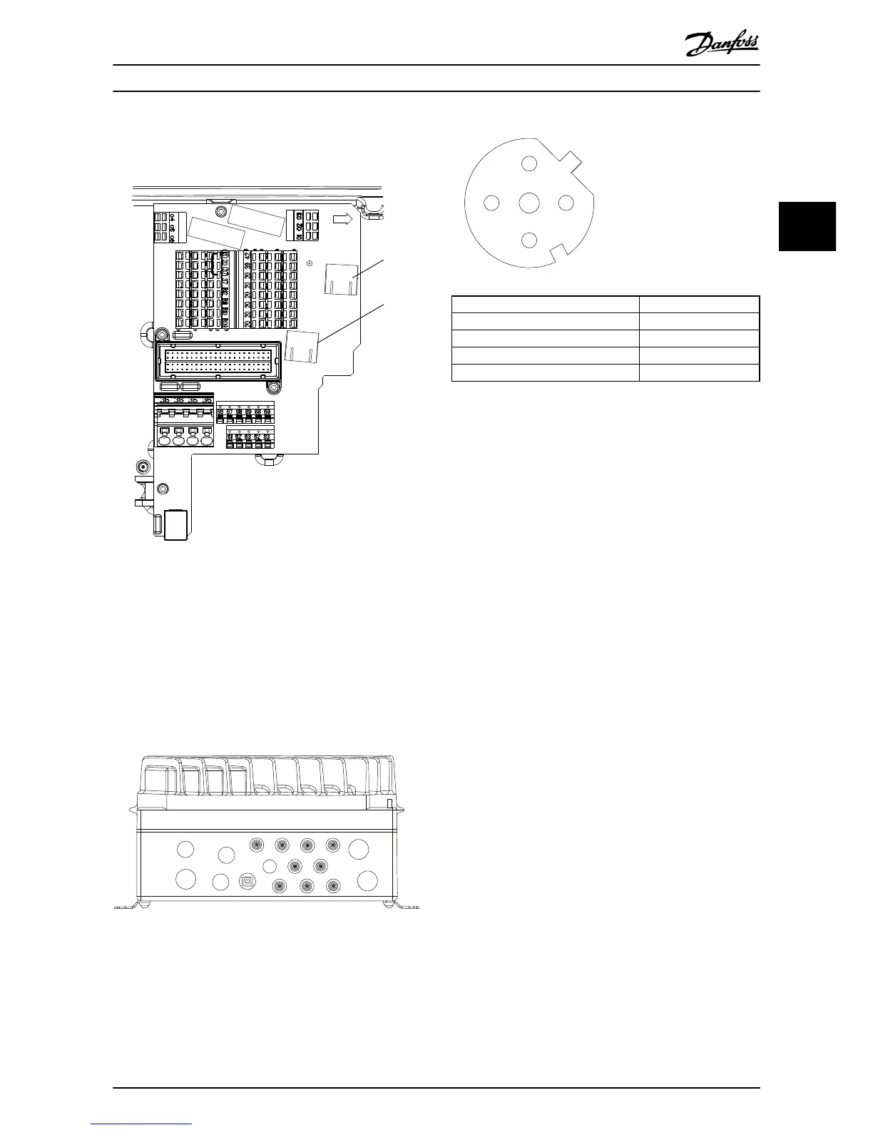
Illustration 3.3 Ethernet Connection on the Control Card
Ethernet ports MK101 and MK102 are placed on the instal-
lation board. MK101 is port 1.
The shield of the two RJ45 connectors is connected to
ground via a RC connection. This guides EMC noise to
ground without risk of a ground loop connection via the
Ethernet cables.
M12 PIN # Signal
1 RX +
2 TX +
3 RX -
4 TX -
Illustration 3.5 M12 Connector
In the pluggable solution the fieldbus is connected directly
to the M12 connection FB1 and FB2 outside the frequency
converter. M12 connector is a “female” connector. FB1 is
connected to port 1. The pluggable solution supports an
easy plug and play solution, where the Ethernet is plugged
to the Ethernet interface. Note that the housing of the
M12 plug is connected directly to ground. If the shield of
the Ethernet cable has to be isolated from ground, a
isolated reduction ring has to be mounted between the
M12 connector and the installation box.
3.1.3
Network
It is of high importance that the media chosen for Ethernet
data transmission are suitable. Normally CAT5e and CAT6
cables are recommended for industrial applications. Both
types are available as unshielded twisted pair and shielded
twisted pair. Shielded cables are recommended for use in
industrial environments and with frequency converters.
A maximum cable-length of 100 m is allowed between
switches.
How to Install Operating Instructions
MG90U302 Danfoss A/S © Rev. 2014-02-27 All rights reserved. 9
3 3