6.4 Control Profile
The frequency converter can be controlled according to
the PROFIdrive profile, or the Danfoss frequency converter
profile. Select the desired control profile in
parameter 8-10 Control Profile. The choice of profile affects
the control and status word only.
6.5 PROFIdrive Control Profile
This section describes the functionality of the control word
and status word in the PROFIdrive profile. Select this
profile by setting parameter 8-10 Control Profile.
6.5.1
Control Word according to PROFIdrive
Profile (CTW)
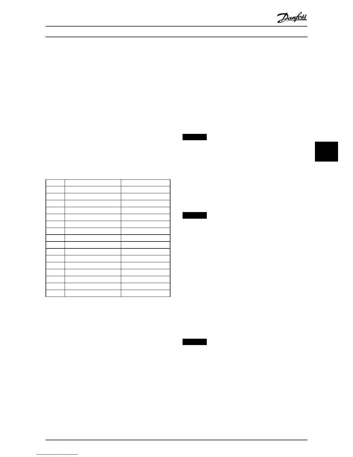
The Control word is used to send commands from a
master (for example, a PC) to a slave.
Bit Bit=0 Bit=1
00 OFF 1 ON 1
01 OFF 2 ON 2
02 OFF 3 ON 3
03 Coasting No coasting
04 Quick stop Ramp
05 Hold frequency output Use ramp
06 Ramp stop Start
07 No function Reset
08 Jog 1 OFF Jog 1 ON
09 Jog 2 OFF Jog 2 ON
10 Data invalid Data valid
11 No function Slow down
12 No function Catch up
13 Parameter set-up Selection lsb
14 Parameter set-up Selection msb
15 No function Reverse
Table 6.13 Control Word Bits
Explanation of the control bits
Bit 00, OFF 1/ON 1
Normal ramp stops using the ramp times of the actual
selected ramp.
Bit 00="0" leads to the stop and activation of the output
relay 1 or 2 if the output frequency is 0 Hz and if [Relay
123] has been selected in 5-40 Function Relay.
When bit 0="1", the frequency converter is in State 1:
“Switching on inhibited”.
Refer to Illustration 6.3.
Bit 01, OFF 2/ON 2
Coasting stop
When bit 01="0", a coasting stop and activation of the
output relay 1 or 2 occurs if the output frequency is 0 Hz
and if [Relay 123] has been selected in 5-40 Function Relay.
When bit 01="1", the frequency converter is in State 1:
“Switching on inhibited”. Refer to Illustration 6.3.
Bit 02, OFF 3/ON 3
Quick stop using the ramp time of 3-81 Quick Stop Ramp
Time. When bit 02="0", a quick stop and activation of the
output relay 1 or 2 occurs if the output frequency is 0 Hz
and if [Relay 123] has been selected in 5-40 Function Relay.
When bit 02="1", the frequency converter is in State 1:
“Switching on inhibited”.
Refer to Illustration 6.3.
Bit 03, Coasting/No coasting
Coasting stop Bit 03="0" leads to a stop.
When bit 03="1", the frequency converter can start if the
other start conditions are satisfied.
NOTICE
The selection in 8-50 Coasting Select determines how bit
03 is linked with the corresponding function of the
digital inputs.
Bit 04, Quick stop/Ramp
Quick stop using the ramp time of 3-81 Quick Stop Ramp
Time.
When bit 04="0", a quick stop occurs.
When bit 04="1", the frequency converter can start if the
other start conditions are satisfied.
NOTICE
The selection in parameter 8-51 Quick Stop Select
determines how bit 04 is linked with the corresponding
function of the digital inputs.
Bit 05, Hold frequency output/Use ramp
When bit 05="0", the current output frequency is being
maintained even if the reference value is modified.
When bit 05="1", the frequency converter can perform its
regulating function again; operation occurs according to
the respective reference value.
Bit 06, Ramp stop/Start
Normal ramp stop using the ramp times of the actual
ramp as selected. In addition, activation of the output relay
01 or 04 if the output frequency is 0 Hz if Relay 123 has
been selected in 5-40 Function Relay. Bit 06="0" leads to a
stop. When bit 06="1", the frequency converter can start if
the other start conditions are satisfied.
NOTICE
The selection in 8-53 Start Select determines how bit 06
is linked with the corresponding function of the digital
inputs.
Bit 07, No function/Reset
Reset after switching off.
Acknowledges event in fault buffer.
When bit 07="0", no reset occurs.
When there is a slope change of bit 07 to "1", a reset
occurs after switching off.
How to Control the Frequenc...
Operating Instructions
MG90U302 Danfoss A/S © Rev. 2014-02-27 All rights reserved. 31
6 6