6.6 Danfoss FC Control Profile
6.6.1 Control Word according to FC Profile
(CTW)
To select Danfoss FC protocol in the control word,
parameter 8-10 Control Profile must be set to [0] frequency
converter profile. The control word is used to send
commands from a master (PLC or PC) to a slave (frequency
converter).
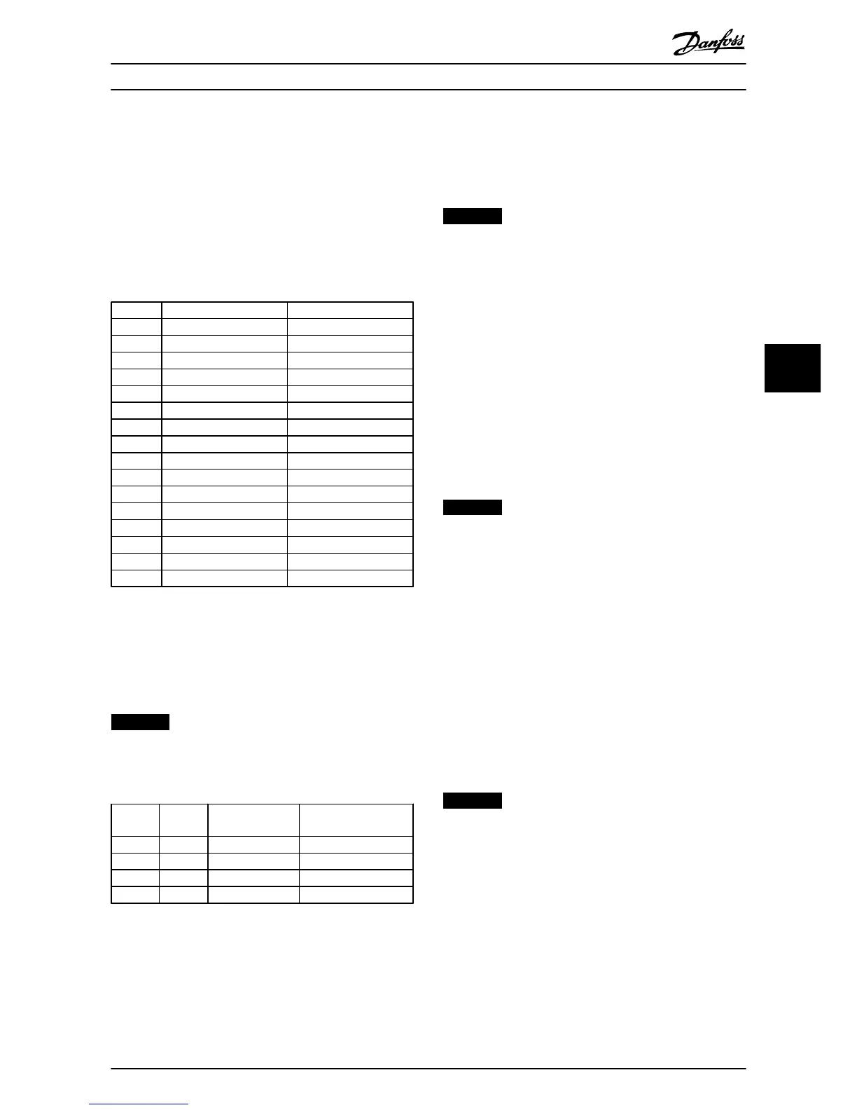
Bit Bit value=0 Bit value=1
00 Reference value external selection lsb
01 Reference value external selection msb
02 DC brake Ramp
03 Coasting No coasting
04 Quick stop Ramp
05 Hold output frequency Use ramp
06 Ramp stop Start
07 No function Reset
08 No function Jog
09 Ramp 1 Ramp 2
10 Data invalid Data valid
11 No function Relay 01 active
12 No function Relay 04 active
13 Parameter set-up selection lsb
14 Parameter set-up selection msb
15 No function Reverse
Table 6.16 Bit Values for FC Control Word
Explanation of the control bits
Bits 00/01 Reference value
Bits 00 and 01 are used to choose between the four
reference values, which are pre-programmed in 3-10 Preset
Reference according to Table 6.17.
NOTICE
In 8-56 Preset Reference Select a selection is made to
define how Bit 00/01 gates with the corresponding
function on the digital inputs.
Bit 01 Bit 00 Programmed
ref. value
Parameter
0 0 1
[0] 3-10 Preset Reference
0 1 2
[1] 3-10 Preset Reference
1 0 3
[2] 3-10 Preset Reference
1 1 4
[3] 3-10 Preset Reference
Table 6.17 Programmed Reference Values for Bits
Bit 02, DC brake
Bit 02=“0” - leads to DC braking and stop. Braking current
and duration are set in 2-01 DC Brake Current and 2-02 DC
Braking Time.
Bit 02=“1” - leads to ramping.
Bit 03, Coasting
Bit 03=“0” - causes the frequency converter to immediately
coast the motor to a standstill.
Bit 03=“1” - enables the frequency converter to start the
motor if the other starting conditions have been fulfilled.
NOTICE
In 8-50 Coasting Select a selection is made to define how
Bit 03 gates with the corresponding function on a digital
input.
Bit 04, Quick stop
Bit 04=“0” - causes a quick stop, ramping the motor speed
down to stop via 3-81 Quick Stop Ramp Time.
Bit 04=“1” - the frequency converter ramps the motor
speed down to stop via 3-81 Quick Stop Ramp Time.
Bit 05, Hold output frequency
Bit 05=“0” - causes the present output frequency (in Hz) to
freeze. The frozen output frequency can only be changed
with the digital inputs (5-10 Terminal 18 Digital Input to
5-15 Terminal 33 Digital Input) programmed to Speed up
and Speed down.
Bit 05=“1” - use ramp.
NOTICE
If Freeze output is active, stop the frequency converter
with
•
Bit 03 Coasting stop
•
Bit 02 DC braking
•
Digital input (5-10 Terminal 18 Digital Input to
5-15 Terminal 33 Digital Input) programmed to
DC braking, Coasting stop, or Reset and coasting
stop.
Bit 06, Ramp stop/start
Bit 06=“0” - causes a stop, in which the motor speed is
ramped down to stop via the selected ramp down
parameter.
Bit 06=“1" - permits the frequency converter to start the
motor, if the other starting conditions have been fulfilled.
NOTICE
In 8-53 Start Select a selection is made to define how Bit
06 Ramp stop/start gates with the corresponding
function on a digital input.
Bit 07, Reset
Bit 07="0" - does not cause a reset.
Bit 07="1" - causes the reset of a trip. Reset is activated on
the signals leading edge, that is, when changing from logic
"0" to logic "1".
Bit 08, Jog
Bit 08="0" - no function.
Bit 08="1" - 3-19 Jog Speed [RPM] determines the output
frequency.
How to Control the Frequenc...
Operating Instructions
MG90U302 Danfoss A/S © Rev. 2014-02-27 All rights reserved. 35
6 6