Bit 09, Selection of ramp 1/2
Bit 09="0" - ramp 1 is active (3-40 Ramp 1 Type to
3-47 Ramp 1 S-ramp Ratio at Decel. Start).
Bit 09="1" - ramp 2 (3-50 Ramp 2 Type to 3-57 Ramp 2 S-
ramp Ratio at Decel. Start) is active.
Bit 10, Data not valid/Data valid
Is used to tell the frequency converter whether it should
use or ignore the control word.
Bit 10="0" - the control word is ignored.
Bit 10="1" - the control word is used. This function is
relevant, because the control word is always contained in
the telegram, regardless of which type of telegram is used.
Thus, it is possible to turn off the control word, if it is not
wished to use it when updating or reading parameters.
Bit 11, Relay 01
Bit 11="0" - relay 01 not activated.
Bit 11="1" - relay 01 activated, provided Control word bit
11 has been chosen in 5-40 Function Relay.
Bit 12, Relay 04
Bit 12="0" - relay 04 has not been activated.
Bit 12="1" - relay 04 has been activated, provided Control
word bit 12 has been chosen in 5-40 Function Relay.
Bit 13/14, Selection of set-up
Bits 13 and 14 are used to choose from the four menu set-
ups according to Table 6.18:
The function is only possible when [9] Multi-Set-up is
selected in 0-10 Active Set-up.
Set-up Bit 14 Bit 13
1 0 0
2 0 1
3 1 0
4 1 1
Table 6.18 Selection of Set-up
NOTICE
In 8-55 Set-up Select a selection is made to define how
Bit 13/14 gates with the corresponding function on the
digital inputs.
Bit 15 Reverse
Bit 15="0" - no reversing.
Bit 15="1" - reversing.
6.6.2
Status Word according to FC Profile
(STW)
The status word is used to inform the master (for example,
a PC) of the operation mode of the slave (frequency
converter).
Refer to chapter 9 Application Examples for an example of a
status word telegram using PPO type 3.
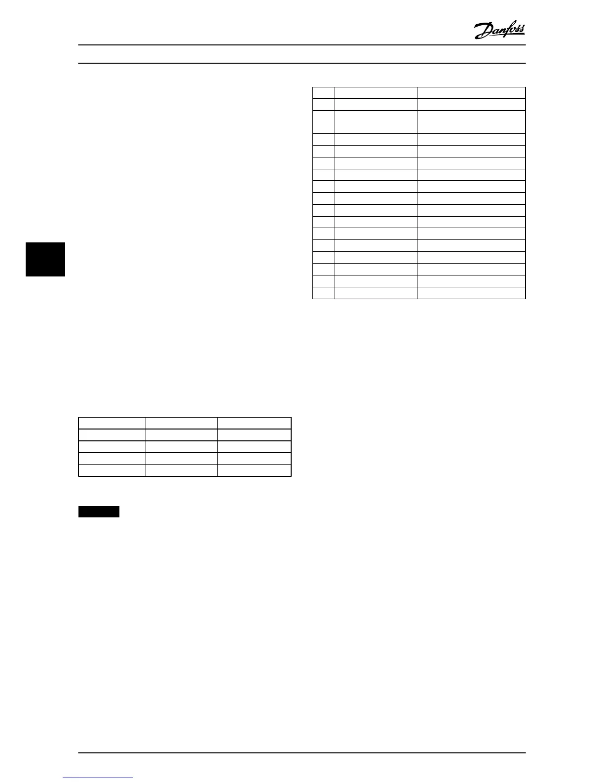
Bit Bit=0 Bit=1
00 Control not ready Control ready
01 Frequency converter
not ready
Frequency converter ready
02 Coasting Enable
03 No error Trip
04 No error Error (no trip)
05 Reserved -
06 No error Triplock
07 No warning Warning
08 Speed reference Speed=reference
09 Local operation Bus control
10 Out of frequency limit Frequency limit ok
11 No operation In operation
12 Frequency converter OK Stopped, autostart
13 Voltage OK Voltage exceeded
14 Torque OK Torque exceeded
15 Timer OK Timer exceeded
Table 6.19 Definition of Status Bits
Explanation of the status bits
Bit 00, Control not ready/ready
Bit 00="0" - the frequency converter has tripped.
Bit 00="1" - the frequency converter controls are ready, but
the power component is not necessarily receiving any
power supply (in case of 24 V external supply to controls).
Bit 01, frequency converter ready
Bit 01="0" - the frequency converter is not ready for
operation.
Bit 01="1" - the frequency converter is ready for operation,
but there is an active coasting command via the digital
inputs or via serial communication.
Bit 02, Coasting stop
Bit 02="0" - the frequency converter has released the
motor.
Bit 02="1" - the frequency converter can start the motor
when a start command is given.
Bit 03, No error/trip
Bit 03="0" - the frequency converter is not in fault mode.
Bit 03="1" - the frequency converter is tripped, and that a
reset signal is required to re-establish operation.
Bit 04, No error/error (no trip)
Bit 04="0" - the frequency converter is not in fault mode.
Bit 04=“1” - there is a frequency converter error but no
trip.
Bit 05, Not used
Bit 05 is not used in the status word.
Bit 06, No error/triplock
Bit 06="0" - the frequency converter is not in fault mode.
Bit 06=“1” - the frequency converter is tripped, and locked.
Bit 07, No warning/warning
Bit 07="0" - there are no warnings.
Bit 07="1" - a warning has occurred.
How to Control the Frequenc...
Operating Instructions
36 Danfoss A/S © Rev. 2014-02-27 All rights reserved. MG90U302
66