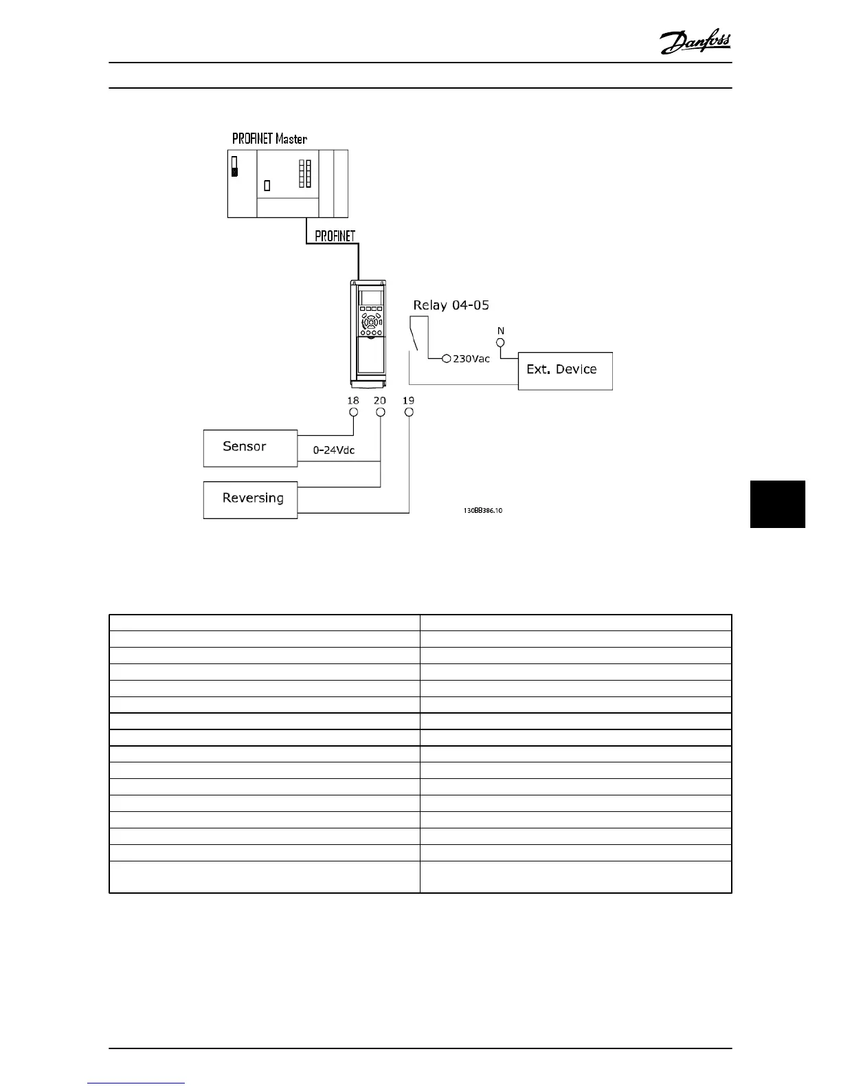
Illustration 9.1
Program the frequency converter as shown in
Table 9.2:
Parameter Setting
4-10 Motor Speed Direction [2] Both directions
5-10 Terminal 18 Digital Input [0] No operation
5-11 Terminal 19 Digital Input [10] Reversing
5-40 Function Relay [36/37] Control word bit 11/12
Parameter 8-03 Control Timeout Time 1 s
Parameter 8-04 Control Timeout Function [2] Stop
Parameter 8-10 Control Profile [0] FC Profile
8-50 Coasting Select [1] Bus
Parameter 8-51 Quick Stop Select [1] Bus
8-52 DC Brake Select [1] Bus
8-53 Start Select [1] Bus
Parameter 8-54 Reversing Select [2] Logic AND
8-55 Set-up Select [1] Bus
8-56 Preset Reference Select [1] Bus
9-16 PCD Read Configuration
[2] Sub index 16-16 Torque [Nm]
[3] Sub indes 16-60 Digital Input
Table 9.2
Application Examples Operating Instructions
MG90U302 Danfoss A/S © Rev. 2014-02-27 All rights reserved. 59
9 9