CBX800 INSTALLATION MANUAL
24
Power to Input
Input Device Signal
Input Device
Reference
Input Device
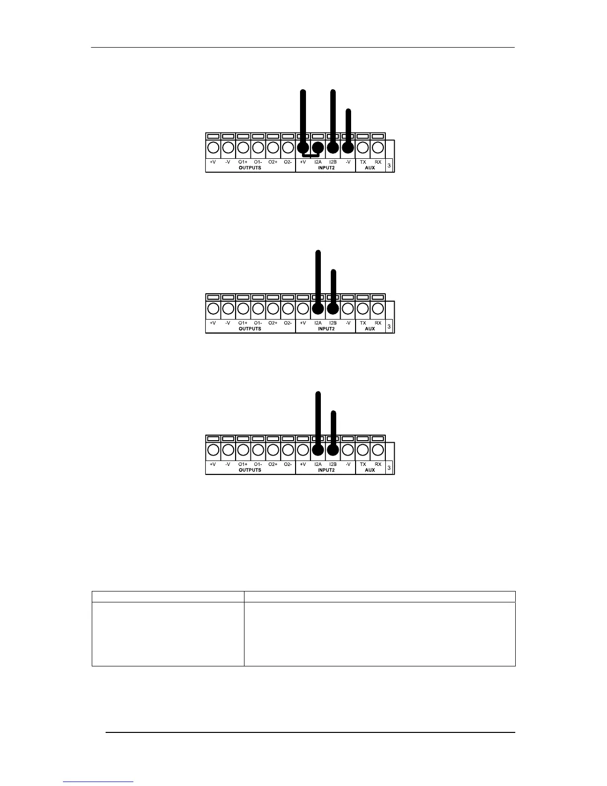
NPN Input 2 Using CBX800 Power
INPUT 2 CONNECTIONS USING EXTERNAL POWER
Pulled down to External
Input Device Reference
Input
Signal
Input Device
Figure 31 - PNP Input 2 Using External Power
Pulled up to External
Input Device Power
Input
Signal
Input Device
Figure 32 - NPN Input 2 Using External Power
OUTPUTS
The two optocoupled general purpose outputs available on the CBX800 spring clamp terminal blocks are
managed by the reader connected to the 25-pin connector. The meaning of the two outputs Output 1 and Output
2 can be defined by the user. They are typically used either to signal the data collection result or, for 2D readers,
to control an external lighting system.
Pinout
Function
+V Power Source - Outputs
O1+ Output 1 +
O1- Output 1 -
O2+ Output 2 +
O2- Output 2 -
-V Power Reference Outputs