EasyManuals Logo

Datalogic Gryphon GBT4400 User Manual

Datalogic Gryphon GBT4400
60 pages
To Next Page IconTo Next Page
To Previous Page IconTo Previous Page
Page #18 background imageLoading...
Page #18 background image
Connecting the Base Station
10 Gryphon™ GBT4400
Using the BC40xx™ Radio Base
Radio Base LEDs
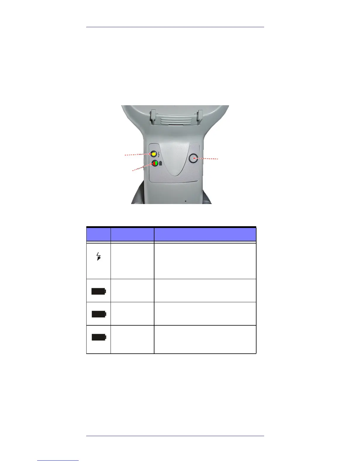
LEDs on the Gryphon Base provide information about the
Base as well as battery charging status, as shown in
Figure 10.
Figure 10. Gryphon Base LEDs
Table 1. Radio Base LEDs
The button can be used to force device connection via the
Datalogic Aladdin Software tool, to force a BT disconnect, and
for paging the scanner when it is activated. Refer to the Gry-
phon I GBT4400 Product Reference Guide (PRG) for a more
detailed explanation.
LED STATUS
Power on /
Data
Yellow On = Base is powered
Yellow Blinking = Base receives data
and commands from the Host or the
Reader.
Charging Red On = the Battery is charging.
Charge com-
pleted
Green On = the Battery is completely
charged.
Charging +
Charge com-
pleted
Red and Green LEDs Off = the Reader
is not correctly placed onto the Base
or charging error.
YELLOW LED
RED LED —
GREEN LED
BUTTON

Questions and Answers:

Question and Answer IconNeed help?

Do you have a question about the Datalogic Gryphon GBT4400 and is the answer not in the manual?

Datalogic Gryphon GBT4400 Specifications

General IconGeneral
ConnectivityBluetooth
IP RatingIP52
Operating Temperature0 to 50 °C / 32 to 122 °F
Storage Temperature-20 to 70 °C / -4 to 158 °F
Dimensions18.1 x 7.1 x 10.0 cm / 7.1 x 2.8 x 3.9 in
Scanner Type2D Imager
BatteryLithium-Ion
Drop Resistance1.8 m (6 ft) to concrete
Light SourceRed LED
Image SensorCMOS
Decode Capabilities1D, 2D, Postal Codes, Stacked Codes
Scan Rate60 frames/sec
InterfaceUSB, RS-232, Keyboard Wedge
Power Supply5 VDC +/- 10%
Humidity5 to 95% non-condensing
Drop Specification1.8 m (6 ft) to concrete

Related product manuals