6.3 ID-NET™
(21x-x0x and 21x-x1x models)
The ID-NET™ connection is used to collect data from several readers to build a multi-point or
a multi-sided reading system; there can be one master and up to 31 slaves connected
together.
The slave readers are connected together using the ID-NET™ interface. Every slave reader
must have an ID-NET™ address in the range 1-31.
The master reader is also connected to the Host on the RS232/RS485 main serial interface.
For a Master/Slave Synchronized layout the External Trigger signal is unique to the system;
there is a single reading phase and a single message from the master reader to the Host
computer. It is not necessary to bring the External Trigger signal to all the readers.
In the Master/Slave Synchronized layout the Master operating mode can only be set to
Phase Mode.
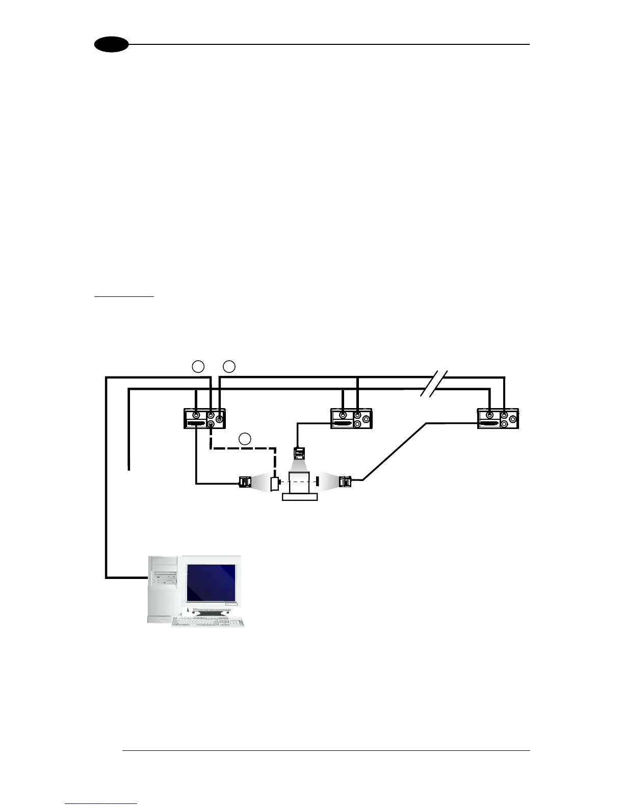
The main, auxiliary, and ID-NET™ interfaces are connected as shown in the figure below.
Figure 93 – ID-NET™ M/S Synchronized Layout
The Master reader can be connected to the CBX series connection box (CBX + BM100
module) or to a QL500 having sw version 2.02.01 and later, with the advantage of the
Backup and Restore configuration function. If the Backup and Restore function is not
required, then a QL300 can be used to connect the master reader.