MATRIX 210™ REFERENCE MANUAL
The same configuration can be made to a Host using a TCP/IP Ethernet interface. In this
case the Master is connected to a CBX500 with BM200/210 Host Interface Module installed.
The TCP/IP Ethernet, auxiliary, and ID-NET™ interfaces are connected as shown in the
figure below.
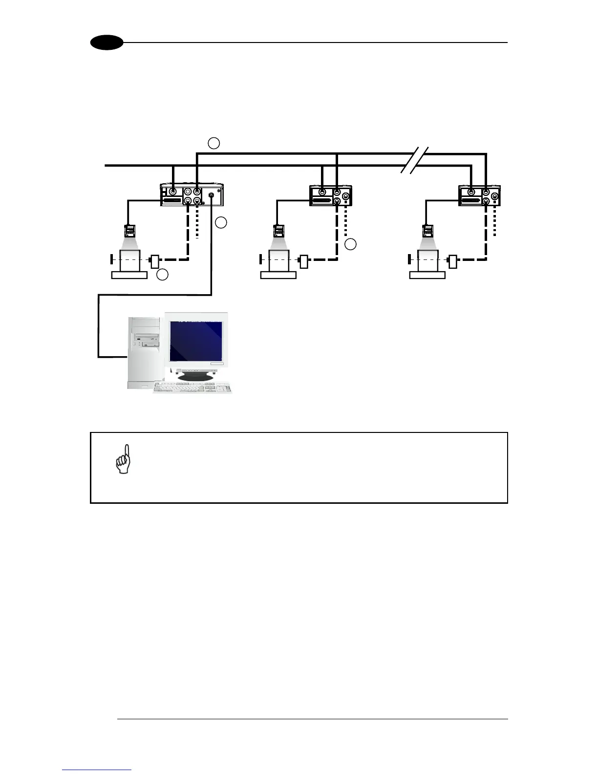
Figure 99 – ID-NET™ M/S Multidata Layout with BM200/210 TCP/IP Ethernet Interface to Host
The auxiliary serial interface of the slave readers can be used in Local Echo
communication mode to control any single reader (visualize collected data)
or to configure it using the VisiSet™ utility.
The ID-NET™ termination resistor switches must be set to ON only in the first
and last CBX connection box.
BM200/210 TCP/IP Ethernet Interface
Auxiliary Serial Interface (Local Echo) (RS232)
External Trigger (for One Shot or Phase Mode)
ID-NET™ (up to 32 devices, max network extension of 1000 m)