Alternatively, the Master scanner can communicate to the Host as a Slave node on a
Fieldbus network. This requires using an accessory Fieldbus interface board installed inside
the CBX500 connection box.
System configuration can be accomplished through the Auxiliary interface of the Master
reader (internal CBX500 9-pin connector) using the VisiSet™ configuration program or Host
Mode programming.
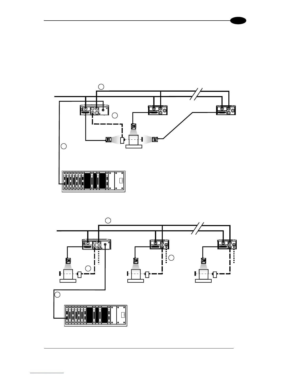
Figure 100 – ID-NET™ Fieldbus M/S Synchronized Layout
Figure 101 – ID-NET™ Fieldbus M/S Multidata
Fieldbus Interface
Auxiliary Serial Interface (Local Echo) (RS232)
External Trigger (for One Shot or Phase Mode)
ID-NET™ (up to 32 devices, max network extension of 1000 m)