12
Single Repeater Installation
A single repeater installation is used in situations where one transmitting station can not
successfully communicate with a receiver, or if a station needs to be farther away from a
receiver than maximum line-of-sight radio link distance. The repeater can also be used as
a signal amplifier for situations in which a signal is weak between a transmitting station
and a receiver.
Verify Transmitter ID
The wireless repeater listens to and communicates with a station transmitter by looking
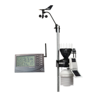
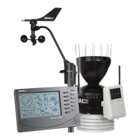
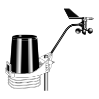
for that station’s unique transmitter ID. Each wireless station, including the Integrated
Sensor Suite (ISS), uses one of eight selectable transmitter IDs. The station’s transmitter
board, known as a Sensor Interface Module (SIM) contains a four-position DIP switch
used to select the station’s transmitter ID.
There are two ways to find out the transmitter ID the station is currently transmitting on:
• Check the DIP switch positions on a station.
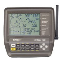
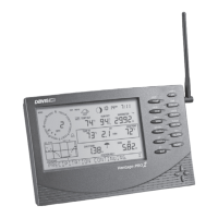
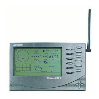
• Check the console for stations currently being received.
Checking DIP Switch Positions on a Station
The Transmitter DIP switch is used to give the station a unique ID. DIP switches #1, 2
and 3 on the transmitter DIP switch control the ID the station uses to transmit on. DIP
switch #4 is used for transmission testing, not for programming the transmitter ID. See
the manual for your Vantage Pro2 Integrated Sensor Suite or transmitting station to locate
the Transmitter ID DIP switch.
To find the transmitter ID on your station:
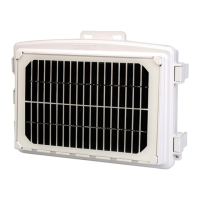
1. Find the white box housing the SIM for your station, open it and locate
the four-position DIP switch, usually located in the upper right-hand
corner of a station’s board.
The default transmitter ID for all stations is 1 and the default position for all of the DIP
switches is down or OFF.
Use this table to determine which transmitter ID the station is using based on the
positions of the #1, 2, and 3 switches on the DIP switch.
ID CODE SWITCH 1SWITCH 2SWITCH 3
1 (default) off off off
2 off off ON
3 off ON off
4 off ON ON
5 ON off off
6 ON off ON
7 ON ON off
8 ONONON
1234
ON
 Loading...