40
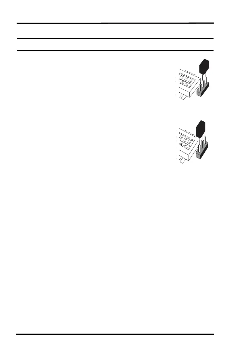
Changing First In Chain Jumper Position
Note: Any repeater with ID A or that does not need to be a first in chain repeater should have the first in chain
jumper left in the default position.
To change a repeater to first in chain:.
1. Remove the black jumper from the top two pins of the first in chain
header
2. Replace the black jumper onto the bottom two pins of the first in chain
header.
Verifying Communication with a
Transmitter and Repeaters
Always start verifying communication at the beginning of each chain,
(repeater A, or any repeater whose jumper position has changed to make it the first in chain).
Once communication between the first in chain repeater, a station, and the subsequent repeaters
has been established, repeat this process for every repeater in the next chain.
See the diagram on the last page of this chapter (“First In Chain Topology with Switch and
Jumper Positions” on page 43) for the transmitter DIP switch settings, repeater DIP switch
settings, and first in chain jumper settings for each repeater in a two chain network.
The process for setting up repeaters and verifying communication between stations and
repeaters is the same for a daisy chain installation (see “Multiple Repeater (Daisy-Chain)
Installation” on page 18) or combination network installation (see “Combination Network
(Multiple Transmitters/Repeaters) Installation” on page 24) except for the number of chains
involved and the position of the first in chain jumper on the header.
In the diagram, repeaters A and C are set up and installed exactly as they have been in previous
installations, with the first in chain header remaining in the default position. However, Repeater
B has the first in chain jumper switched to the ON position so that it is the first repeater in a
second chain.
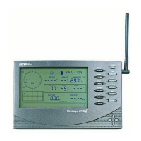
Verifying Repeater Communication with a Console
On the Console in Setup Mode Screen 2: Configuring Transmitter IDs:
1. Select the Transmitter ID using the first repeater chain. If the station is not already turned on
with its station type selected, do so now. Turn the station on by pressing the up arrow until
“ON” displays on the screen. Change the station type by pressing GRAPH until the correct
station type displays.
Default
(Normal)
Position
First in Chain
Position
 Loading...