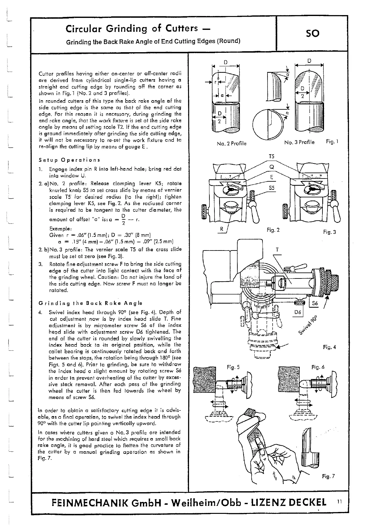
No. 2 Profile
No. 3 Profile
Fig. 1
15
Fig. S
Circular Grinding of Cutters -
so
Grinding the Back Rake Angle of End Cutting Edges (Round)
Cutter profiles having either on-center or off-center radii
are derived from cylindrical single-lip cutters having a
straight end cutting edge by rounding off the corner as
shown in Fig. 1 (No.2 and 3 profiles).
In rounded cutters of this type the bock rake angle of the
side cutting edge is the some as that of the end cutting
edge. For this reason it is necessary, during grinding the
end rake angle, that the work fixture is set at the side rake
angle by means of setting scale 12. If the end cutting edge
is ground immediately after grinding the side cutting edge,
it will not be necessary to re-set the work fixture and to
re-align the cutting lip by means of gauge E -
Setup Operations
1.
Engage index pin R into left-hand hale; bring red dot
into window U.
2.
a)No. 2 profile: Release clamping lever KS; rotate
knurled knob 55 to set crass slide by means of vernier
scale T5 for desired radius (to the right); tighten
clamping lever K5, see Fig. 2. As the radiused corner
is required to be tangent to the cutter diameter, the
amount of offset "a is:a =
Example:
Given r = .06" (1.5 mm); D = .30" (8 mm)
o = .15" (4 mm) —.06" (1.5 mm) = .09" (2.5 mm)
2. b)No. 3 profile: The vernier scale 15 of the crass slide
must be set at zero (see Fig. 3).
3.
Rotate fine adjustment screw F to bring the side cutting
edge of the cutter into light contact with the face of
the grinding wheel. Caution: Do not injure the land of
the hide cuffing edge. Now screw F must no longer be
rotated.
Grinding the Back Rake Angle
4.
Swivel index head through
90
(see Fig. 4). Depth of
cut adjustment now is by index head slide T. Fine
adjustment is by micrometer screw S6 of the index
head slide with adjustment screw D6 tightened. The
end of the cutter is rounded by slowly swivelling the
index head back to its original position, while the
collet bearing is continuously rotated bock and forth
between the stops, the rotation being through
1800
(see
Figs. 5 and 6). Friar to grinding, be sure to withdraw
the index head a slight amount by rotating screw 56
in order to prevent overheating of the cutter by exces-
sive stock removal. After each pass of the grinding
wheel the cutter is then fed towards the wheel by
means of screw 56.
In order to obtain a satisfactory cutting edge it is advis-
able, as a final operation, to swivel the index head through
90
0
with the cutter lip pointing vertically upward.
In cases where cutters given a No.3 profile are intended
for the machining of hard steel which requires a small bath
rake angle, it is good practice to flatten the curvature of
the cutter by a manual grinding operation as shown in
Fig. 7.
F8NMECHANIK GmbH - Weilheim/Obb - LIZENZ DECKEL
11