Fig. 1
Fig. 3
Twist Drill Grinding Attachment
I
so
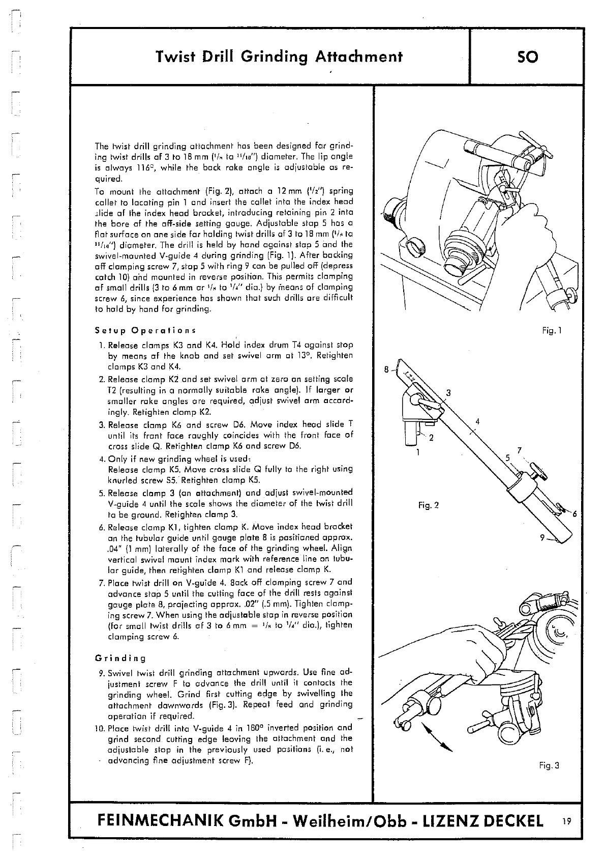
The twist drill grinding attachment has been designed for grind-
ing twist drills of 3 to 18 mm
('R
to "ho") diameter. The lip angle
is always 116
0
, while the back rake angle is adjustable as re-
quired.
To mount the attachment (Fig. 2), attach a 12 mm
('/2
"
) spring
callet to locating pin 1 and insert the collet into the index head
slide of the index head bracket, introducing retaining pin 2 into
the bore of the aft-side setting gauge. Adjustable stop 5 has a
not surface an one side for holding twist drills of 3 to 18 mm ('/ to
''ho)
diameter. The drill is held by hand against stop 5 and the
swivel-mounted V-guide 4 during grinding (Fig. 1). After backing
off clamping screw 7, stop with ring 9 can be pulled off (depress
catch 10) and mounted in reverse position. This permits clamping
of small drills 13 to 6 m or
1
1m
to '/" dia.) by means of clamping
screw 6, since experience has shown that such drills are difficult
to hold by hand for grinding.
Setup Operations
1.
Release clamps K3 and K4. Hold index drum T4 against stop
by means of the knob and set swivel arm at 13
0
. Retighten
clamps K3 and K4.
2.
Release clamp K2 and set swivel arm at zero an setting scale
T2 (resulting in a normally suitable rake angle). If larger or
smaller rake angles are required, adjust swivel arm accord-
ingly. Retighten clamp K2.
3.
Release clamp K6 and screw DO. Move index head slide I
until its front face roughly coincides with the front face of
cross slide Q. Retighten clamp K6 and screw Do.
4.
Only if new grinding wheel is used:
Release clamp K5. Move cross slide 0 fully to the right using
knurled screw
ss:
Retighten clamp KS.
5.
Release clamp 3 (on attachment) and adjust swivel-mounted
V-guide 4 until the scale shows the diameter of the twist drill
to be ground. Retighten clamp 3.
6.
Release clamp K1, tighten clamp K. Move index head bracket
an the tubular guide until gauge plate B is positioned approx.
.04" (1 mm) laterally of the face of the grinding wheel. Align
vertical swivel mount index mark with reference line on tubu-
lar guide, then retighten clamp K1 and release clamp K.
7.
Place twist drill on V-guide 4. Back off clamping screw 7 and
advance stop 5 until the cutting face of the drill rests against
gauge plate 8, projecting apprax..02" (.5 mm). Tighten clamp-
ing screw 7. When using the adjustable stop in reverse position
(for small twist drills of 3 to 6 m =
'ho
to
1/i"
dia.), tighten
clamping screw 6.
Grin di otg
9.
Swivel twist drill grinding attachment upwards. Use fine ad-
justment screw F to advance the drill until it contacts the
grinding wheel. Grind first cutting edge by swivelling the
attachment downwards (Fig. 3). Repeat feed and grinding
operation if required.
10.
Place twist drill into V-guide 4 in 180
0
inverted position and
grind second cutting edge leaving the attachment and the
adjustable stop in the previously used positions (I. e., not
advancing fine adjustment screw F).
FEINMECHANIK GmbH - Weilheim/Obb - LIZENZ DECKEL
19