L1
LI__
nfl
IF
1yi\
lit
fl/A
F
7
I
frfl
/1
2
2
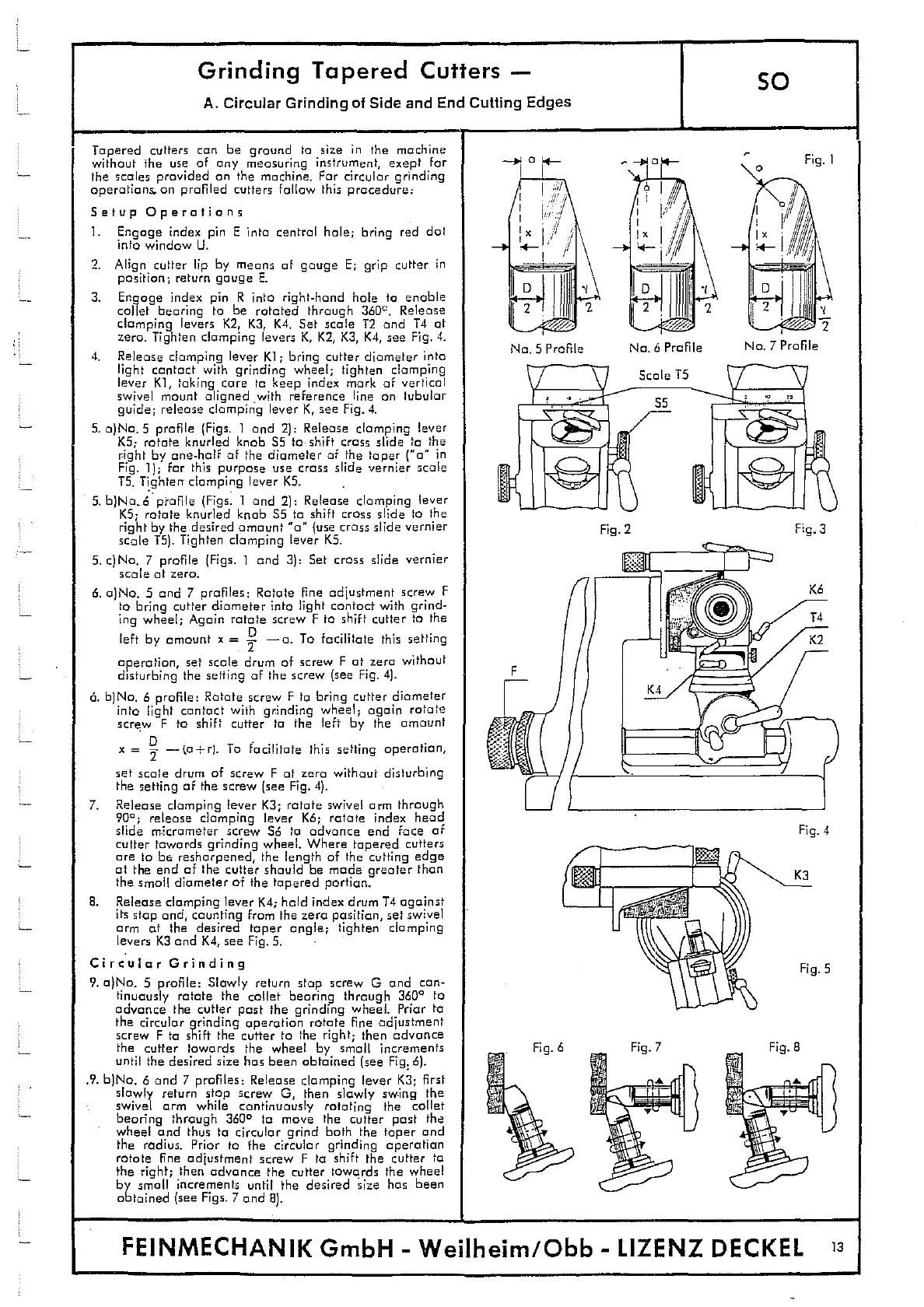
No.5 Profile
Na. 6 Profile
Fig.]
Na. 7 Profile
Fig.2
Fig.3
FP
Fig. 4
I. S
10
41
Fic.
I-
Grinding Tapered Cutters -
so
A. Circular Grinding of Side and End Cutting Edges
Tapered cutters can be ground to size in the machine
without the use of any measuring instrument, exept for
the scales provided on the machine. For circular grinding
operations, on profiled cutters follow this procedure:
Setup Operations
1. Engage index pin E into central hole; bring red dot
into window U.
2. Align cutter lip by means of gouge E; grip cutter in
position; return gouge E.
3. Engage index pin R into right-hand hole to enable
collet bearing to be rotated through
3600.
Release
clomping levers K2, K3, K4. Set scale T2 and T4 at
zero Tighten clamping levers K, K2, K3, K4, see Fig. 4.
4.
Release clamping lever Ki; bring cutter diameter into
light contact with grinding wheel; tighten clomping
lever KI, taking care to keep index mark of vertical
swivel mount aligned with reference line on tubular
guide; release clomping lever K, see Fig. 4.
5. o)Na. 5 profile (Figs. I and 2): Release clomping lever
KS
;
rotate knurled knob 55 to shift cross slide to the
right by one-half of the diameter of the taper ('o in
Fig. 1); for this purpose use cross slide vernier scale
T5. Tighten clamping lever KS. -
5. b)Na,6 ptauile (Figs. I and 2): Release clamping lever
KS; rotate knurled knob 55 to shift cross slide to the
right by the desired amount 'a" (use crass slide vernier
scale T5). Tighten clomping lever K5.
5. c)Na. 7 profile (Figs. 1 and 3): Set cross slide vernier
scale at zero.
6. a)No. 5 and 7 profiles: Rotate fine adjustment screw F
to bring cutter diameter into light contact with grind-
ing wheel; Again rotate screw F to shift cutter to the
left by amount x =
—a. To facilitate this setting
operation, set scale drum of screw F at zero without
disturbing the setting of the screw (see Fig. 4).
6.
b)Na. 6 profile: Rotate screw F to bring cutter diameter
into light contact with grinding wheel
;
again rotate
screw F to shift cutter to the left by the amount
x =
—to—
,
0. To facilitate this setting operation,
set scale drum of screw F at zero without disturbing
the setting of the screw (see Fig. 4).
7.
Release clamping lever K3; rotate swivel arm through
900; release clomping lever Ko; rotate index head
slide rnicrameter screw 56 to advance end face of
cutter towards grinding wheel. Where tapered cutters
are Ia be resharpened, the length of the cutting edge
at the end of the cutter should be made greater than
the small diameter of the tapered portion.
8.
Release clamping lever K4; hold index drum 14 against
its stop and, counting from the zero position, set swivel
arm at the desired taper angle; tighten clamping
levers K3 and K4, see Fig. 5.
Circular Grinding
9.
a)Na. S profile: Slowly return stop screw 0 and con-
tinuously rotate the collet bearing through 360° to
advance the cutter past the grinding wheel. Prior to
the circular grinding operation rotate fine ad1ustment
screw F to shift the cutter to the right
;
then advance
the cutter towards the wheel by small increments
until the desired size has been obtained (see Fig. 6).
.9. b)Na. 6 and 7 profiles: Release clamping lever K3; first
slowly return stop screw 0, then slowly swing the
swivel arm while continuously rotating the collet
bearing through 360
0
to move the cutter past the
wheel and thus to circular grind bath the taper and
the radius. Prior to the circular grinding operation
rotate fine adjustment screw F to shift the cutter to
the right; then advance the cutter towards the wheel
by small increments until the desired size has been
obtained (see Figs. 7 and 8).
FEINMECHANIK GmbH - Weilheim/Obb - 1.IZENZ DECKEL
13