I
Servicing the Index Head Bracket
J
SO
17
General
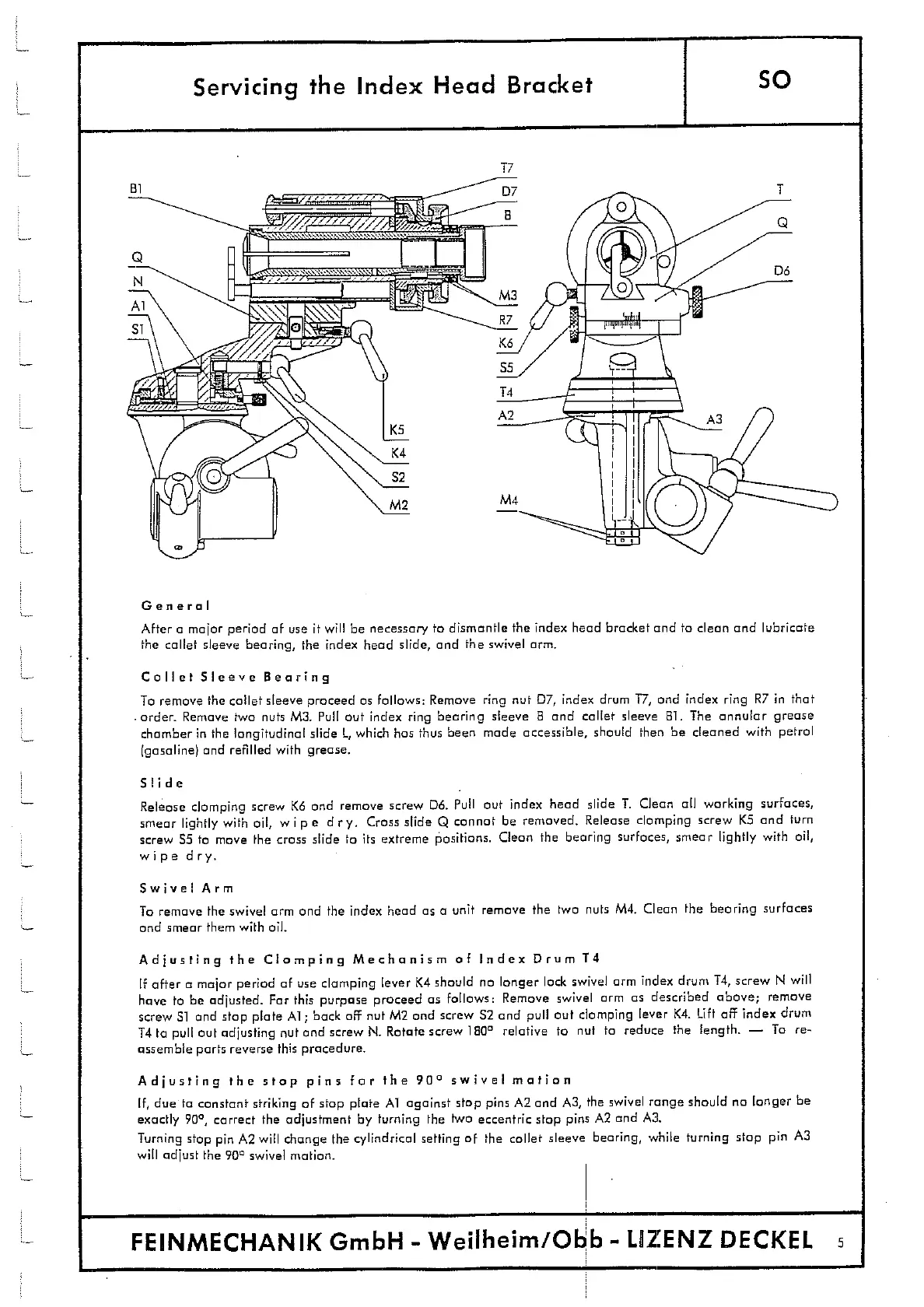
After a major period of use it will be necessary to dismantle the index head bracket and to clean and lubricate
the collet sleeve bearing, the index head slide, and the swivel arm.
Collet Sleeve Bearing
To remove the collet sleeve proceed as follows: Remove ring nut D7, index drum 17, and index ring R7 in that
order. Remove two nuts M3. Pull out index ring bearing sleeve B and collet sleeve BI. The annular grease
chamber in the longitudinal slide L which has thus been made accessible, should then be cleaned with petrol
(gasoline) and refilled with grease.
Slide
Release clamping screw K6 and remove screw D6. Pull out index head slide T. Clean all working surfaces,
smear lightly with oil, wipe dry. Crass slide Q cannot be removed. Release clomping screw KS and turn
screw
35
to move the cross slide to its extreme positions. Clean the bearing surfaces, smear lightly with oil,
wipe dry.
Swivel Arm
To remove the swivel arm and the index head as a unit remove the two nuts M4. Clean the bearing surfaces
and smear them with oil.
Adjusting the Clamping Mechanism of Index Drum 14
If after a major period of use clamping lever (4 should no longer lock swivel arm index drum T4, screw N will
have to be adjusted. For this purpose proceed as follows: Remove swivel arm as described above; remove
screw 31 and stop plate Al; back off nut M2 and screw 32 and pull out clamping lever K4. Lift off index drum
T4 to pull out adjusting nut and screw N. Rotate screw 180
0
relative to nut to reduce the length. - To re-
assemble ports reverse this procedure.
Adjusting the stop pins for the
900
swivel motion
If, due to constant striking of stop plate Al against stop pins A2 and A2, the swivel range should no longer be
exactly 90
0
, correct the adjustment by turning the two eccentric stop pins A2 and A3.
Turning stop pin A2 will change the cylindrical setting of the collet sleeve bearing, while turning stop pin A3
will adjust the
900
swivel motion.
I
FEINMECHANIK GmbH - Weilheim/Obb - LIIZENZ DECKEL