Circular Grinding of Cutters
-
so
Grinding the Back Rake Angle of Side Cutting Edges
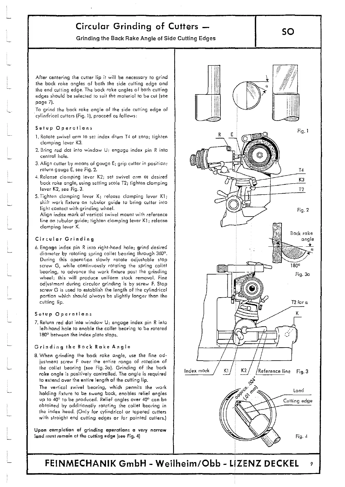
After centering the cutter lip it will be necessary to grind
the back rake angles of both the side cutting edge and
the end cutting edge. The back rake angles of both cutting
edges should be selected to suit the material to be cut (see
To grind the back rake angle of the side cutting edge of
cylindrical cutters (Fig. 1), proceed as follows:
Setup Operations
Fig 1
1.
Rotate swivel arm to set index drum 14 at zero; tighten
R
clamping lever K3.
2.
Bring red dot into window U; engage index pin R into
central hole.
.
no
3.
Align cutter by means of gauge E
;
grip cutter in position;
:
return gauge E, see Fig. 2.
14
4.
Release clamping lever K2; set swivel arm at desired
K3
back rake angle, using setting scale 12; tighten clomping
lever K2, see Fig. 3.
T2
5.
Tighten clamping lever K; release clamping lever Ki;
-\
shift work fixture an tubular guide to bring cutter into
C
light contact with grinding wheel-
Fig. 2
Align index mark of vertical swivel mount with reference
line on tubular guide tighten clamping lever K1 ; release
clamping lever K.
4
Back rake
Circular Grinding
angle
& Engage index pin R into right-hand hole; grind desired
-
-
>-- -
a
diameter by rotating spring collet bearing through 360
0
.
During this operation slowly rotate adjustable stop
screw 0, while continuously rotating the spring collet
..
lBOa
bearing, to advance the work fixture past the grinding
V
- --
Fig. 3a
wheel; this will produce uniform stack removal. Fine
adjustment during circular grinding is by screw F. Stop
screw G is used to establish the length of the cylindrical
r
portion which should always be slightly longer than the
-
cutting lip.
-
T2 for a
Setup Operations
K
7. Return red dot into window U; engage index pin R into
left-hand hole to enable the collet bearing to be rotated
180 between the index plate stops.
U
Grinding the Back Rake Angle
B. When grinding the back rake angle, use the fine ad-
justment screw F over the entire range of rotation of
the collet bearing (see Fig. 3a). Grinding of the back
Index mark
Ki
K2
Reference line Fig. 3
rake angle is positively controlled. The angle is required
to extend over the entire length of the cutting lip.
The vertical swivel bearing, which permits the work
0
Land
holding fixture to be swung back, enables relief angles
R
up to
400
to be produced. Relief angles over 40
0
can be
Cutting edge
obtained by additionally rotating the collet bearing in
the index head. (Only for cylindrical or tapered cutters
with straight end cutting edges or for painted cutters.)
Upon completion of grinding operations a very narrow
land must remain at the cutting edge (see Fig. 4)
Fig. 4
F
FEINMECHANIK GmbH - Wejlhejm/Obb - LffZIENZ DECKEL
9