Fig. 3
Pi- 1
Fig. 5
so
Grinding Tapered Cutters -
(B) Grinding the Back Rake Angie of Side and End Cutting Edges (Straight)
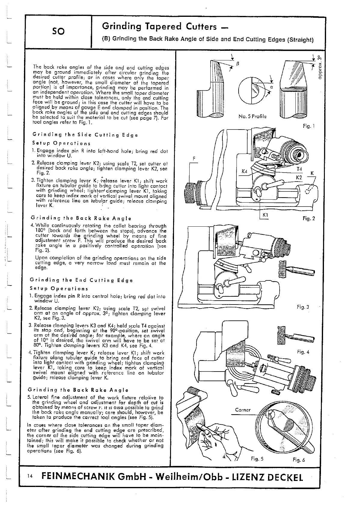
The bock rake angles of the side and end cutting edges
may be ground immediately after circular grinding the
desired cutter profile; or in cases where only the taper
angle (not, however, the small diameter of the tapered
portion) is of importance, grinding may be performed in
an independent operation. Where the small taper diameter
must be held within close tolerances, only the end cutting
face will be ground
;
in this case the cutter will have to be
aligned by means of gauge E and clamped in position. The
back rake angles of the side and end cutting edges should
be selected to suit the material to be cut (see page 7). For
tool angles refer to Fig. 1.
Grinding the Side Cutting Edge
Setup Operations
1.
Engage index pin R into left-hand hale; bring red dot
into window U.
2.
Release clamping lever K2; using scale T2, set cutter at
desired back rake angle
;
tighten clomping lever K2, see
Fig. 2.
3.
Tighten clamping lever K; "release lever Ki
;
shift work
fixture on tubular guide to bring cutter into light contact
with grinding wheel; tightenclomping lever Ki, taking
care to keep index mark of vertical swivel mount aligned
with reference line on tubular guide; release clamping
lever K.
Grinding the Bock Rake Angie
4.
While continuously rotating the collet bearing through
1600 (bock and forth between the stops), advance the
cutter towards the grinding wheel by means of fine
adjustment screw F. This will produce the desired bock
rake angle in a positively controlled operation (see
Fig. 2).
Upon completion of the grinding operations on the side
cutting edge, a very narrow land must remain at the
edge.
Grinding the End Cutting Edge
Setup Operations
1.
Engage index pin R into central hale
;
bring red dot into
window U.
2.
Release clomping lever K2; using scale T2, set swivel
arm at an angle of approx. 30; tighten clamping lever
K2, see Fig. 3.
3.
Release clomping levers K3 and K4; hold scale T4 against
its stop and, beginning
of
the 90
0
-positian, set swivel
arm at the desired angle; for example, where an angle
of
100
is desired, the swivel arm will have to be set at
80
0
. Tighten clamping levers K3 and K4, see Fig. 4.
4.
Tighten clamping lever K; release lever KI; shift work
fixture along tubular guide to bring end face of cutter
into light contact with grinding wheel; tighten clamping
lever K1, taking care to keep index mark of vertical
swivel mount aligned with reference line on tubular
guide; release clamping lever K.
Grinding the Back Rake Angle
5.
Lateralfine adjustment of the work Fixture relative to
the grinding wheel and adjustment for depth of cut is
obtained by means of screw i
-
. iris aisa passible to grind
the back rake angle manually; care should, however, be
taken to produce the correct tool angles (see Fig. 5).
In cases where close tolerances an the small taper diam-
eter after grinding the end cuffing edge are prescribed,
the corner of the side cuffing edge will have to be main-
tained; this will make it possible to check whether or not
the small taper diameter was changed during grinding
operations (see Fig. 6).
c
I
1
14
FEINMECHANIK GmbH — Weilheim/Qbb — LIZENZ DECKEL