Dectron, Inc. March 2012
DECTRON
DSH/DSV/RSH/DBH/RBH Series Dehumidifier Owner’s Manual
Data subject to change without notice.
276
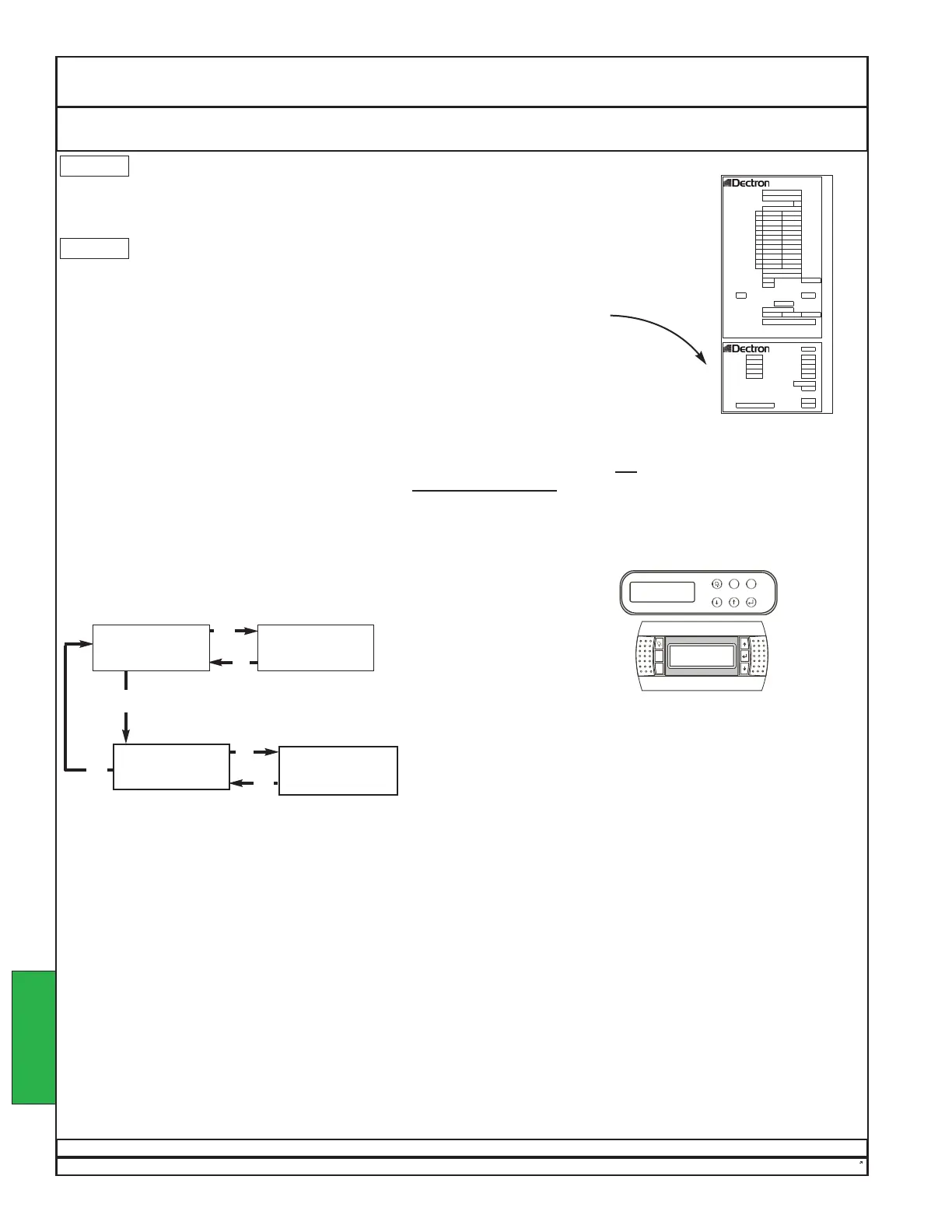
Operation Set-Point Adjustment
The operating set points are viewed and adjusted as shown below.
If asked for a password, enter 1793 for units made before April 2005.
For units made since April 2005, enter 17 or 1793.
To clear the password, select YES when prompted to log off.
GO TO
SET POINTS
HUMIDITY SET bbb%
RETURN AIR SET ddd F
POOL 1 SET eee F
POOL 2 SET ggg F
MAIN MENU
SCROLL DOWN
FOR OPTIONS
Default Screen
HUMIDITY aaa / bbb %
ROOM AIR ccc / ddd F
Press
↓↓
repeatedly to reach screen below.
Press
↵↵
to move the cursor around the screen.
aaa is the present indoor relative humidity.
bbb% is the relative humidity set point. If a change is desired,
press
↵↵
as needed tomove the cursor to aaa%, then press
↑↑
or
↓↓
to
change the set point.
ccc is the present room air temperature.
ddd F is the room air temperature set point. If achange is desired,
press
↵↵
as needed to move the cursor to ddd F, then press
↑↑
or
↓↓
to change the set point.
eee F is the pool #1 temperature set point. If achange is desired,
press
↵↵
as needed to move the cursor to eee F, then press
↑↑
or
↓↓
to change the set point.
ggg F is the pool #2 temperature set point. If achange is desired,
press
↵↵
as needed to move the cursor to ggg F, then press
↑↑
or
↓↓
to change the set point.
MODEL #:
SERIAL #:
I.D.
D
ELECTRICAL RATING
460 V ac, 3 ph, 60 Hz
LRA RLA
BLOWER MOTOR HP FLA
BLOWER MOTOR HP FLA
BLOWER MOTOR HP FLA
COND. FAN MOTOR HP FLA
COND. FAN MOTOR HP FLA
PUMP MOTOR HP FLA
ENTHALPY MOTOR HP FLA
ELECTRIC HEATER kW A
Max. L.A.T. (°F)
SERVICE POWER
SPACE HEATING COIL
PSIG Max.
MCA A MAX. FUSE/CKT. BKR.*
15
A
R-22 FACTORY CHARGE
lbs
AIR VOLUME CFM
BELT SIZE
WIRING DIAGRAM
REFRIGERANT DESIGN PRESSURES: HIGH/LOW 300/150 PSIG
FABRIQUÉ AU CANADA / MADE IN CANADA
POOL # 1: ft² POOL # 3: ft²
E.W.T.: °F E.W.T.: °F
POOL # 2: ft² POOL # 4: ft²
E.W.T.: °F E.W.T.: °F
AIR TEMP.: °F R.H.: %
R-22 TOTAL SYSTEM CHARGE:
lbs
MAX. LENGTH OF REF. LINES (ONE WAY) ft
BETWEEN D.O.T. & REMOTE CONDENSER:
LINE SIZE:
AIR COOLED COND. MODEL #:
HOT GAS: in
LIQUID: in
Set points should be kept near the values that appear on the unit nameplate.
Each unit is carefully sized to match the expected load, as specified in the original order.
Attempting to operate a unit far from rated conditions can have unexpected results, such
as excessive evaporation, condensation in unexpected locations, and other problems. If
set points must be changed, air-temperature set point and water-temperature set point
must be changed together.
NOTE: Unless the unit submittal data specifies special operating conditions, do not
attempt
to operate the unit at a space temperature below 78°F (25.6°C).
{
NOTE: In the image above and the discussion
at right, “bbb”, “ddd”, “eee”, and “ggg”
are placeholders.
Your screen will show the set points
for your unit.
NOTE: The test “Pool 2 Set . . . gggF” is
optional and may not appear on all units.
NOTICE
NOTICE
Risk of unit damage.
Unless the unit submittal data specifies special operating conditions, do not
attempt to operate the unit at a space temperature below 78°F (25.6°C). See
further instructions below.
Risk of uncontrolled evaporation.
Improper changes to air and water temperatures can profoundly affect the
rate of pool evaporation. See further instructions below.
OPERATION
↵↵
↵↵
Esc
Esc
Esc
 Loading...