DSE Model 5320 Automatic Mains Failure & Instrumentation System Operators Manual
38 Part No. 057-014 5320 OPERATING MANUAL ISSUE 5.1 18/06/2007 ADM
8 ELECTRICAL CONNECTIONS
Connections to the Module are via plug and sockets.
8.1 CONNECTION DETAILS
The following describes the connections and recommended cable sizes to the 8 plugs and sockets on the rear of
the Module. See rear panel layout
FIG 6.
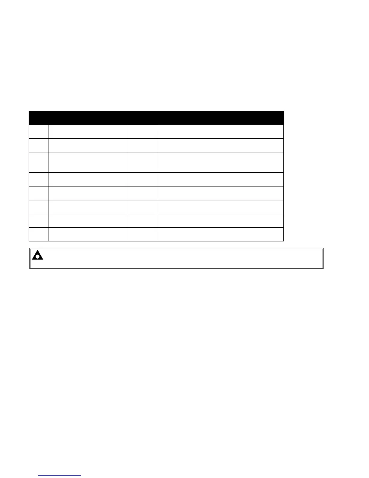
8.1.1 PLUG “A” 8 WAY
PIN
No
DESCRIPTION CABLE
SIZE
NOTES
1 DC Plant Supply Input
(Negative)
2.5mm²
AWG 13
2 DC Plant Supply Input
(Positive)
2.5mm²
AWG 13
(Recommended Maximum Fuse 21A)
3 Emergency Stop Input 2.5mm²
AWG 13
Plant Supply Positive. Also supplies fuel &
start outputs.
(Recommended Maximum Fuse 32A)
4 Fuel relay Output 2.5mm²
AWG 13
Plant Supply Positive from pin 3. 16 Amp
rated.
5 Start relay Output 2.5mm²
AWG 13
Plant Supply Positive from pin 3. 16 Amp
rated.
6 Auxiliary Output relay 1 1.0mm²
AWG 18
Plant Supply Positive. 5 Amp rated.
7 Auxiliary Output relay 2 1.0mm²
AWG 18
Plant Supply Positive. 5 Amp rated.
8 Auxiliary Output relay 3 1.0mm²
AWG 18
Plant Supply Positive. 5 Amp rated.
NOTE:- When the module is configured for CAN operation, FUEL, START and AUXILIARY output
requirements may be different. Refer to CAN and DSE Wiring for further information.