Rooster™ Sensor100 USER MANUAL
Rooster
TM
Sensor100 USER MANUAL 62320MN000-A04 7
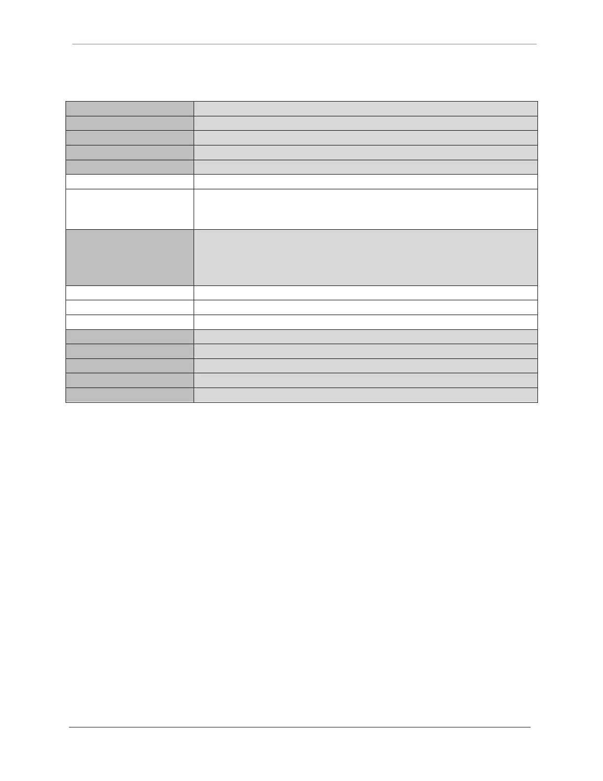
Technical Specifications
Connection and Wiring Information
Use the backplate label as a reference to prepare the wiring harness for the Rooster
TM
. Once the
wire harnesses are pulled through the opening and attached to Rooster™, then the front touch
panel assembly can be snapped into place.
Degree Controls recommends 18-24 AWG for all wiring connections to the input and output
connectors. Both the sensor and power supply connections have been prepared for you, and
merely need to be pulled through the cutout and connected to Rooster™ as pictured above. The
Rooster
TM
Sensor100 has additional input and output capabilities for night setback and alarm
output relay.
The I/O connectors present on the Rooster
TM
have some pins deactivated as these are reserved
for future Rooster
TM
models designed for more advanced control functionality:
o Output Connectors, Pins 5-6
o Input Connectors, Pins 7-10
These pins should be non-connected.