Rooster™ Sensor100 USER MANUAL
Rooster
TM
Sensor100 USER MANUAL 62320MN000-A04 9
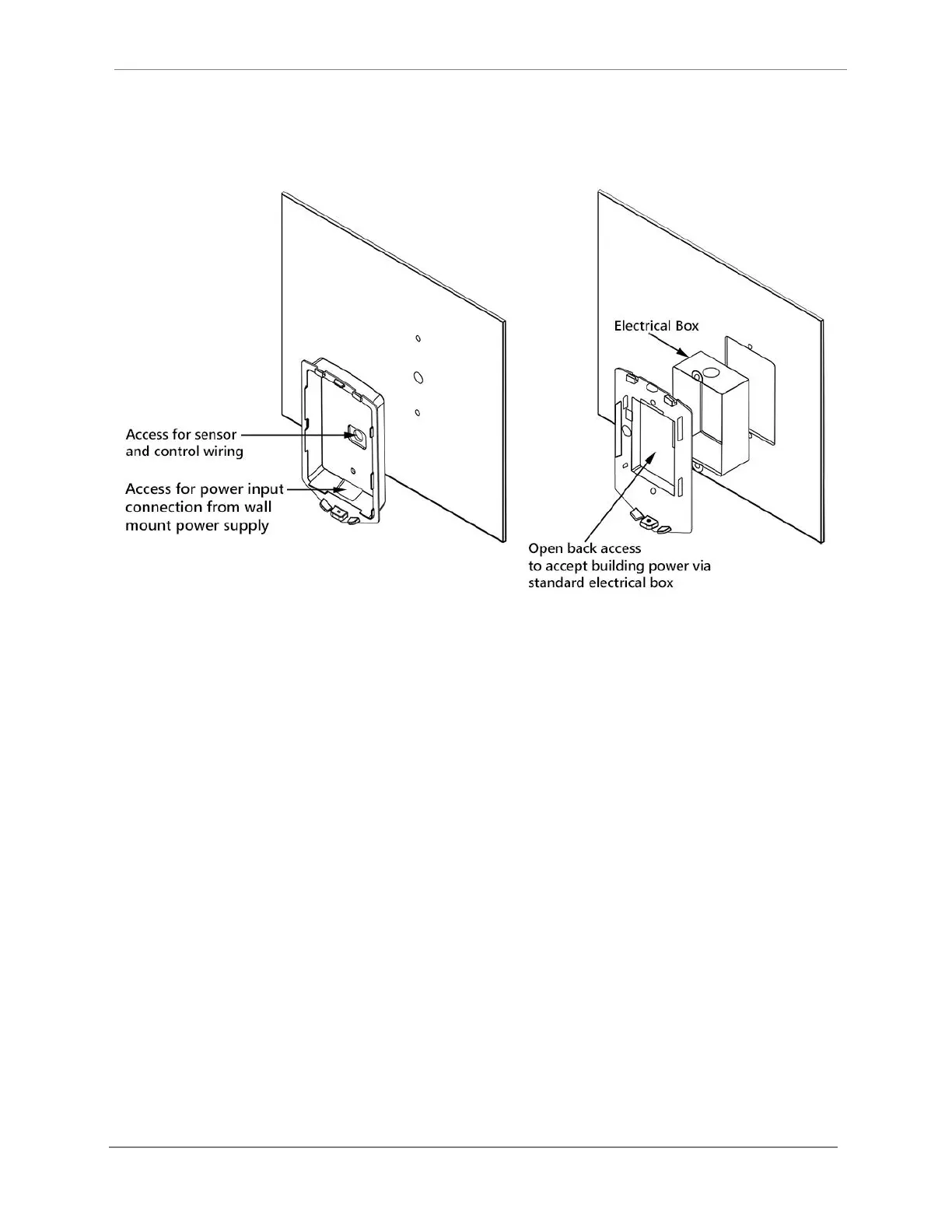
2. Semi-Flush: This back plate sits partially inside a standard electrical gang box, allowing the
Rooster
TM
to be recessed and sit approximately 15mm [0.6”] proud of the mounting surface.
Self-tapping screws secure it, and there is open back access to accept building power.
Figure 1 Wall Mount (left), Semi-Flush Mount (right) - for Alarm Module
Installation Procedure
1. Determine mounting locations for the Rooster
TM
alarm module and sensor.
2. Choose alarm module mounting method: Wall Mount or Semi-Flush.
3. Mark the surface where the Rooster
TM
alarm module will be located, and make the
necessary drills/cutout.
4. Secure back plate.
5. Mount the sensor. See below for sensor installation.
6. Feed power and sensor wire harnesses through the opening(s) and make connections to
the Rooster
TM
alarm module. Make any other optional connections to the alarm module.
7. Align top of alarm module with tabs on back plate, and secure in place with captive
screw at bottom of alarm module.