Rooster™ Sensor100 USER MANUAL
Rooster
TM
Sensor100 USER MANUAL 62320MN000-A04 10
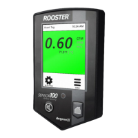
Figure 2 Wall Mount Back Plate Mounting
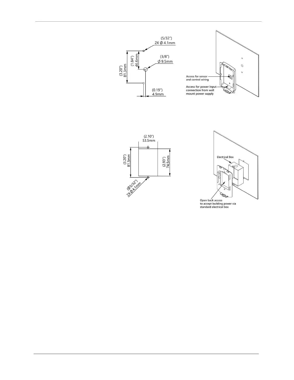
Figure 3 Semi-Flush Back Plate Mounting
Probe Sensor
The probe sensor should be located in your duct system in the best laminar (stable) flow
possible. Good sensor placement and ASHRAE best practices should be followed. The sensor
should be placed at least two duct diameters away from duct elbows and constrictions. Please
see below for °C Clamp specifications and installation instructions.
°C Clamp and Sensor Installation:
1. Mark the sensor hole, and screw positions, per Step 1 of °C Clamp installation figure,
below.
2. Drill a 17/32” (14mm) hole through the surface you wish to install the sensor.
3. Drill two pilot holes for the °C Clamp fastening screws. (°C Clamp, Degree Controls P/N:
64500AS011)
4. Secure the °C Clamp with two screws (not provided).
5. Insert the sensor into the °C Clamp and adjust the sensor’s insertion depth (use the
printed ruler on the sensor’s body for reference), ensuring that the airflow indicators
(arrows on the blue or orange head; see Airflow Direction below) are facing in the
intended direction.