V0608, 4.9
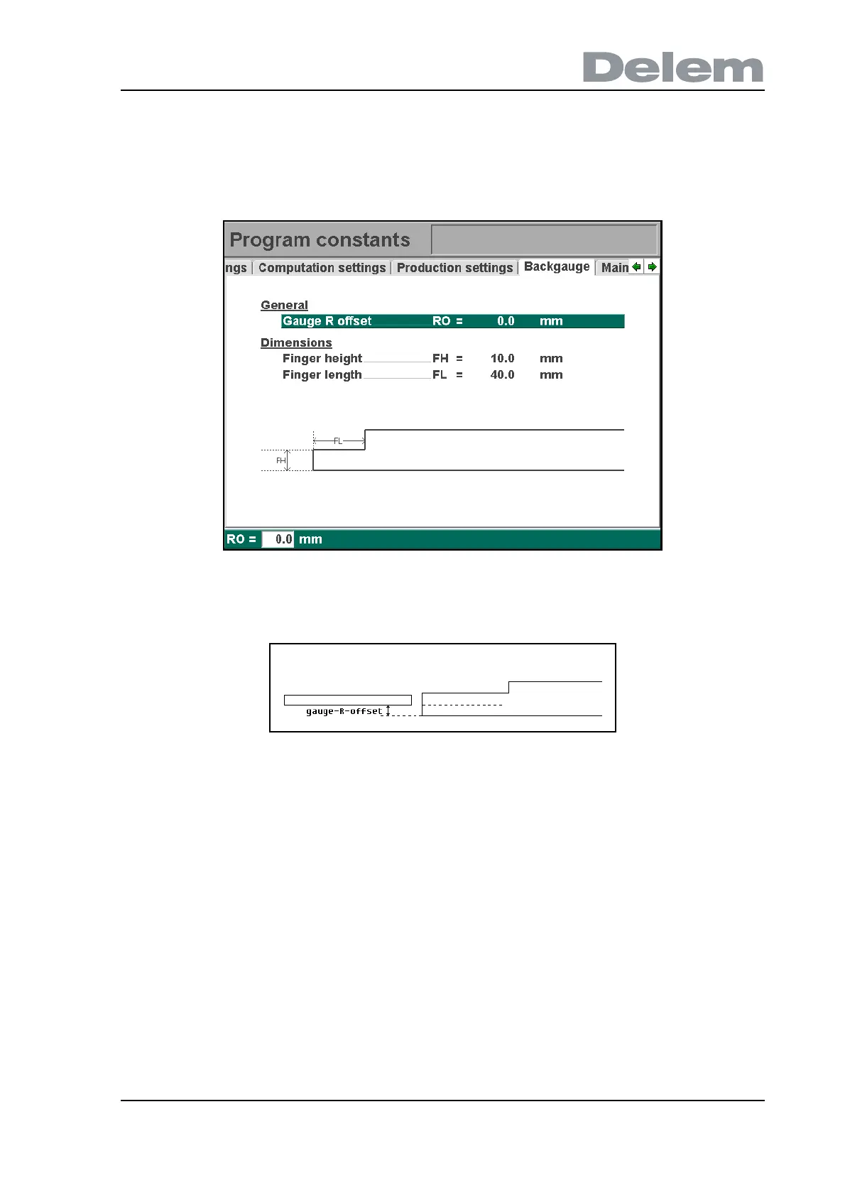
4.7. Backgauge dimensions
With these finger dimensions the R-axis movement and workpiece/backgauge collision can be
computed.
4.g
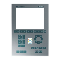
Gauge R offset . . . . . . . . . . . . . . . . . . . . . . . . . . . . . . . . . . . . . . . . . . ..RO =
An offset value for the R-axis can be set if the backgauge is positioned against the sheet
edge and the X-axis position is outside the die safety zone.
4.h
A negative value gives a lower backgauge position. This offset is only valid for gauge
position 0.
Finger height . . . . . . . . . . . . . . . . . . . . . . . . . . . . . . . . . . . . . . . . . . . ..FH
The height of the default finger level.
Finger length . . . . . . . . . . . . . . . . . . . . . . . . . . . . . . . . . . . . . . . . . . . ..FL
The length of the first finger level.