Do you have a question about the Delem DA-58T and is the answer not in the manual?
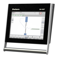
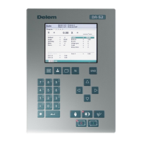
Describes the physical appearance and primary interface of the DA-58T control unit.
Details the integrated Start and Stop buttons within the touch screen interface.
Explains the availability and purpose of the USB port on the control unit for external devices.
Introduces the main screen layout and navigation of the DA-Touch control system.
Outlines the initial steps for creating a bend program, from product creation to production.
Covers features designed to assist users with programming, such as help text and listboxes.
Explains the purpose and functionality of the Products mode for managing programs.
Describes the overview of the program library and its components in the Products mode.
Details the process of selecting and loading products from the library for further operations.
Guides users on initiating a new graphical product program.
Explains how to begin creating a new numerical program for bending.
Covers the essential functions for managing existing products and programs.
Explains how to prevent accidental changes to finished products or programs.
Describes how to efficiently search for products using the filter feature.
Details how to navigate, create, and manage product directories.
Explains how to select products from network directories.
Outlines setting up general properties before creating a product drawing.
Describes the process of creating a 2D profile for a product.
Explains how to define and adjust the properties of lines within a product drawing.
Details how to set specific properties for different types of bends.
Introduces the process of configuring tools for machine setup.
Describes the general steps for setting up and selecting tools.
Explains how to choose punches and dies from the tool library.
Introduces the process of determining and simulating the bend sequence.
Explains how to navigate and select bends within the bend sequence screen.
Details the process of unfolding a product to determine the bend sequence.
Describes how to manually determine or change the bend sequence.
Explains how to manually adjust finger positions for optimal bending.
Covers the parameters that control the bend sequence computation.
Introduces the Assignments screen and its role in bend sequence computation.
Details general assignment parameters like optimization degree and front extend ratio.
Explains backgauge-related parameters for bend sequence computation.
Describes how to view a graphical overview of the entire bend sequence.
Introduces the process of creating and modifying CNC programs.
Explains the specific parameters for each bend within a program.
Covers auxiliary functions that can be programmed for bending operations.
Highlights parameters that are not automatically recalculated after changes.
Introduces the automatic mode for executing bend programs bend by bend.
Explains the available parameters and corrections within the automatic mode.
Describes the different visual displays available within the automatic mode.
Details the main view showing numerical bend data and corrections.
Explains the 'All bends' view, which displays bend data in a table format.
Describes the full-screen graphical visualization of the bend process.
Details the 'Macro' view for displaying large axes values.
Explains the manual positioning view for controlling axes.
Covers viewing and modifying correction values for angles and axes.
Describes the diagnostics view for monitoring axes and system status.
Explains how to apply general corrections for bumping bends.
Introduces the manual mode for programming and testing single bends.
Explains the available parameters within the manual mode.
Details how parameters are programmed and visualized in manual mode.
Describes the 'Macro' view for displaying large axes values in manual mode.
Explains how to manually control and move the machine axes.
Details the step-by-step procedure for manually moving axes using the slider.
Explains how to teach axis positions by manual movement.
Covers viewing and modifying corrections for bends programmed in manual mode.
Describes the diagnostics view for monitoring axes states in manual mode.
Explains how to view the status of inputs and outputs.
Details the zoomed view for selected I/O pins.
Introduces the Settings mode for configuring product and program parameters.
Covers general settings like language, units, and keyboard layout.
Explains how to program and manage material properties.
Details functions for backing up and restoring products, tools, and settings.
Guides on backing up product programs to storage media.
Explains how to restore product programs from storage media.
Guides on backing up tools (punches, dies) to storage media.
Explains how to restore tools from storage media.
Covers backing up and restoring tables and general settings.
Describes how to navigate backup directories.
Details program-specific settings, including angle correction databases.
Explains how to set default values for various parameters.
Covers settings related to bend allowance calculation and force factors.
Details settings for production mode, such as stock counting and step change.
Explains how production time is calculated based on axes and handling.
Covers settings for display time, time format, and date format.
Mentions network settings, marked as "to be described".
Introduces the Machine mode for configuring machine characteristics.
Explains how to program, edit, and delete punches used in the machine.
Guides on creating a new punch profile by defining its shape and ID.
Details the parameters for defining a standard punch.
Explains the parameters for programming a hem bend punch.
Details the parameters for an air and hem bend punch.
Explains the parameters for a punch designed for big radius bends.
Explains how to program, edit, and delete bottom dies.
Guides on creating a new die by defining its shape and ID.
Details the parameters for defining a standard die.
Explains the parameters for a hem bend die.
Details the parameters for an inside hem bend die.
Explains the parameters for an air and hem bend U die.
Covers machine-specific settings like backgauge finger dimensions and collision computation.
Explains how to draw custom shapes for tools and machine components.
Covers maintenance functions like hours, strokes, and touchscreen calibration.
Details how to view system information, software versions, and update functionality.
| Brand | Delem |
|---|---|
| Model | DA-58T |
| Category | Controller |
| Language | English |