Steps
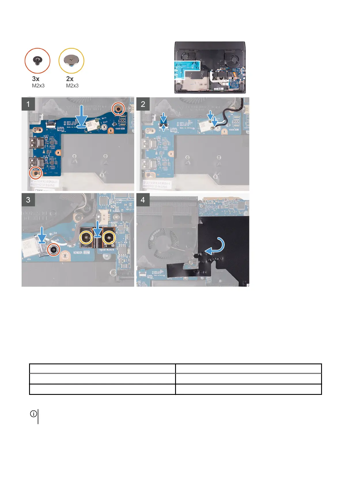
1. Using the alignment post, place the left I/O-board on the palm-rest assembly.
2. Replace the two screws (M2x3) that secure the left I/O-board to the palm-rest assembly.
3. Connect the power-button assembly-cable to the left I/O-board and close the latch.
4. Connect the antenna cables to the wireless card.
The following table provides the antenna-cable color scheme for the wireless card supported by your computer.
Table 3. Antenna-cable color scheme
Connectors on the wireless card Antenna-cable color
Main (white triangle) White
Auxiliary (black triangle) Black
5. Using the alignment pins, connect the left I/O-board cable on the left I/O-board and the system board.
NOTE: The I/O-board cable is polarity sensitive. To prevent damage to your computer ensure that the MB UMT end of
the cable is connected to the system board.
6. Replace the two screws (M2x3) that secure the left I/O-board cable to the left I/O-board and the system board.
7. Place the wireless-card bracket on the wireless card .
35