8. Remove the power-adapter port.
9. Remove the headset port.
10. Remove the left fan.
11. Remove the right fan.
12. Remove the heat pipe.
About this task
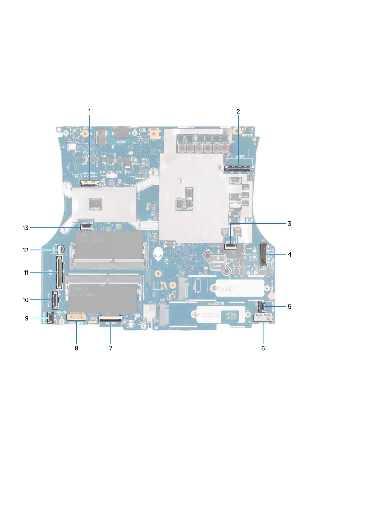
The following image indicates the connectors on your system board.
1. Camera cable
2. Display cable
3. Left Tron-light cable
4. Power-button cable
5. Right fan cable
6. Battery cable
7. Keyboard-controller board cable
8. Speaker cable
9. Left fan cable
10. Headset port cable
11. I/O-board cable
12. Power button cable
13. Right Tron-light cable
The following image(s) indicate the location of the system board and provides a visual representation of the removal procedure.
52
Removing and installing components
 Loading...