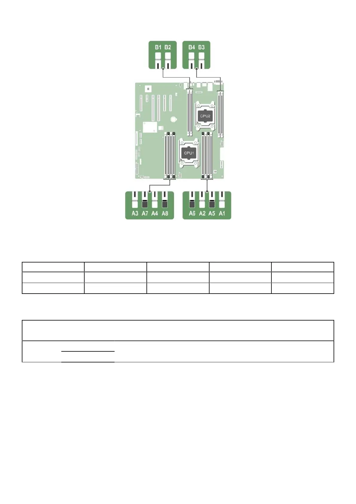
Figure 55. Memory socket locations
Memory channels are organized as follows:
Table 30. Memory channels
Processor Channel 0 Channel 1 Channel 2 Channel 3
Processor 1 slots A1 and A5 slots A2 and A6 slots A3 and A7 slots A4 and A8
Processor 2 slot B1 slot B2 slot B3 slot B4
The following table shows the memory populations and operating frequencies for the supported configurations.
Table 31. Memory populations and operating frequencies
DIMM Type
DIMMs
Populated/
Channel
Voltage
Operating Frequency
(in MT/s)
Maximum DIMM Rank/
Channel
RDIMM
1
1.2 V 2400, 2133, and 1866 Single rank or dual rank
2
General memory module installation guidelines
Your system supports Flexible Memory Configuration, enabling the system to be configured and run in any valid chipset
architectural configuration. The following are the recommended guidelines for best performance:
● LRDIMMs, and RDIMMs must not be mixed.
● x4 and x8 DRAM based DIMMs can be mixed. For more information, see the Mode-specific guidelines section.
● A maximum of three single- or dual-rank RDIMMs can be populated in a channel.
● If memory modules with different speeds are installed, they operate at the speed of the slowest installed memory module(s)
or slower depending on system DIMM configuration.
● Populate DIMM sockets only if a processor is installed. For single-processor systems, sockets A1 to A8 are available. For
dual-processor systems, sockets A1 to A8 and sockets B1 to B4 are available.
108 Installing and removing system components

 Loading...