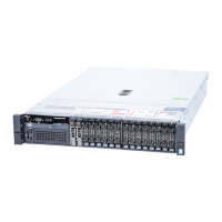
Figure 79. Removing the LED module—four cabled hard drive chassis
1
LED module 2 screw (2)
3 slot on the chassis
Figure 80. Removing the LED control panel board—four cabled hard drive chassis
1
screw (2) 2 control panel connector cable
3 control panel board 4 USB connector cable
5 stando on the chassis (2)
124 Installing and removing system components