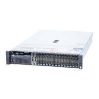
Figure 22. Installing the cooling shroud
1 cooling shroud 2 guide on the cooling shroud
3 guide pin on the chassis wall
Next step
Follow the procedure listed in After working inside your system.
Related links
Removing the optional front bezel
Installing the optional front bezel
System memory
Your system supports DDR4 ECC unbuered DIMMs (UDIMMs).
NOTE
: MT/s indicates memory module speed in Mega Transfers per second.
Memory bus operating frequency can be 1600 MT/s, 1866 MT/s, 2133 MT/s, or 2400 MT/s depending on the following factors:
• System prole selected (for example, Performance Optimized, Custom, or Dense Conguration Optimized)
• Maximum supported memory module frequency of the processors
The system contains four memory sockets — two sets of 2–sockets each. Each 2–socket set is organized into one channel. In each 2-
socket set, the rst socket release lever is marked white and the second socket release lever is marked black.
62
Installing and removing system components
 Loading...