Cable routing
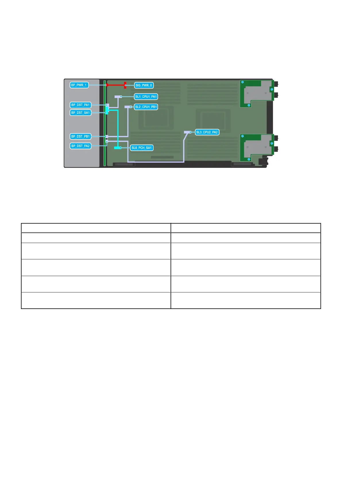
Figure 32. SATA/PCIe cabling diagram of configuration 3 - 6 x 2.5-inch Universal backplane with on board SATA +
on board PCIe
Table 8. Connector descriptions for on board SATA + on board PCIe
From To
BP_PWR_1 (backplane power connector) SIG_PWR_0 (system board power connector)
BP_DST_PA1 (backplane PCIe 1 connector, cable marking BP
PA1)
SL1_CPU1_PA1 (signal connector on the system board, cable
marking MB SL1)
BP_DST_SA1 (backplane SATA connector, cable marking BP
SA1)
SL6_PCH_SA1 (signal connector on the system board, cable
marking MB SL6)
BP_DST_PB1 (backplane PCIe 2 connector, cable marking BP
PB1)
SL2_CPU1_PB1 (signal connector on the system board, cable
marking MB SL2)
BP_DST_PA2 (backplane PCIe 3 connector, cable marking BP
PA2)
SL3_CPU2_PA2 (signal connector on the system board, cable
marking MB SL3)
40 Installing and removing system components

 Loading...


