Remove the top cover from the node
Steps
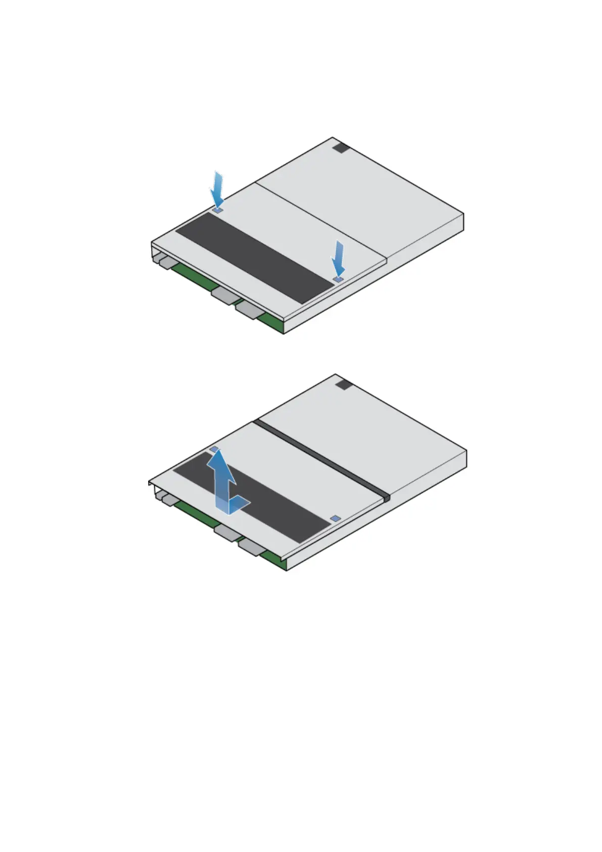
1. While pushing down the two blue release buttons, slide the top cover towards the rear of the system, until it stops.
Figure 107. Releasing the top cover
2. Lift the top cover upward, and remove it from the node.
Figure 108. Removing the top cover
Transfer parts from the faulted node to the replacement
node
Transfer the following components from the faulted node to the corresponding locations in the replacement node.
To help ensure the correct placement in the enclosure, transfer only one component at a time.
• Transfer the power supply.
• Transfer the I/O modules and fillers.
• Transfer the embedded module without removing the 4-port card.
• Transfer the internal M.2 boot modules without removing them from the adapters.
• Transfer DIMMs.
• Transfer internal fans.
• Transfer the internal battery backup module.
Base enclosure service procedures
77

 Loading...


