PS6500 Hardware Maintenance Basic Array Information
1-3
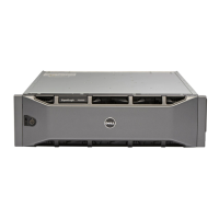
Hardware Status LEDs
Figure 1-4 shows a detail view of the hardware status LEDs.
Figure 1-4: PS6500 Hardware Status LEDs
Hardware status LEDs. These LEDs indicate when hardware problems occur. These LEDs can also be seen
when the bezel is installed. See Hardware Status LEDs on page 1-3.
Disk drive LEDs. These LEDs indicate when a drive is present and disk drive activity. See Disk Drive LEDs on
page 2-1.
Cam screws. The two cam screws secure the array front panel to the chassis cover.
Chassis handles. The handles are used to pull out the chassis, opening the cover and exposing the disk drives,
channel cards, and EIP card.
Figure 1-4 Description
Indicator Status Description
Array power Off No power.
Green Normal operation.
Yellow Array is not turned on (standby mode).
Power supply and
cooling modules
Off Normal operation.
Flashing orange Module removed.
Orange Power supply failure, fan failure, or upper or lower temperature
limit exceeded.
Control modules Off Normal operation.
Flashing orange Module removed or upper or lower temperature limit exceeded.
Orange Module failure.
Disk drives Off Normal operation.
Flashing yellow One or more disk drive failures.
Yellow Array is running in standby mode.
Channel cards Off Normal operation.
Flashing yellow Channel card removed.
Yellow Channel card failure.
Figure 1-3 Description