1–1
1 Basic Array Information
This chapter includes information about the location and basic operation of the replaceable components in a
PS6500 storage array, technical specifications, power on and off operations, and how to return failed components.
Field Replaceable Components
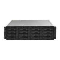
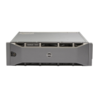
The PS6500 array includes the field-replaceable components shown in Figure 1-1.
Figure 1-1: Field-Replaceable Components
You access disk drives, channel cards, and the EIP card from the front of the array. You must remove the bezel and
open the chassis cover to access these components. See Removing and Installing the Bezel on page 1-8 and
Opening and Closing the Chassis Cover on page 1-9.
You access control modules and power supply and cooling modules from the rear of the array.
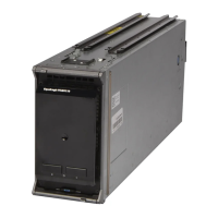
Figure 1-1 Description
Control modules. A PS6500 array includes two control modules.
Power supply and cooling modules. A PS6500 array includes three power supply and cooling modules.
EIP card. A PS6500 array includes one EIP card.
Channel cards. A PS6500 array includes two channel cards.
Disk drives. A PS6500 array includes 48 disk drives. Drives are protected with spare disks and RAID.