PS6500 Hardware Maintenance Maintaining Control Modules
3-2
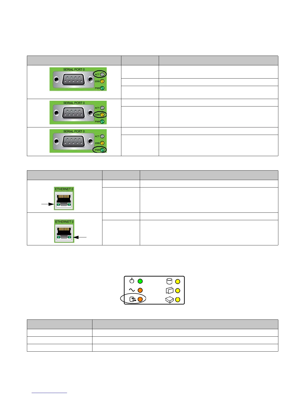
• Each Ethernet port has two LEDs that show the network interface status. See Figure 3-1 and Table 3-2.
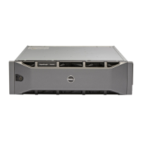
In addition, on the bottom front of the array, in the center, the control module hardware status LED (circled in
Figure 3-2) shows the status of all the control modules. Table 3-3 describes their status conditions.
Figure 3-2: Control Module Hardware Status LED on Front Panel
Table 3-1: Control Module LED Descriptions
LED Location Color Description
ACT LED
Off No power, secondary control module is not synchronized
with active control module, or error condition.
Green Active control module (serving network I/O).
Orange Secondary control module. Cache is synchronized with
active control module.
ERR LED
Off Normal operation or no power.
Red Array is starting up or error condition.
PWR LED
Off No power.
Green Power.
Table 3-2: Ethernet Port LED Descriptions
Ethernet Port LEDs Color Description
Left side of each port. Off No power or not connected to network.
Green Connected to network.
Right side of each port. Off No power, not transmitting, or not receiving.
Green Transmitting or receiving.
Table 3-3: Control Module Hardware Status LED States
Color Description
Off Normal operation.
Flashing orange Control module removed or temperature limit exceeded.
Orange Control module failure.