PS6500 Hardware Maintenance Maintaining the EIP Card
6-2
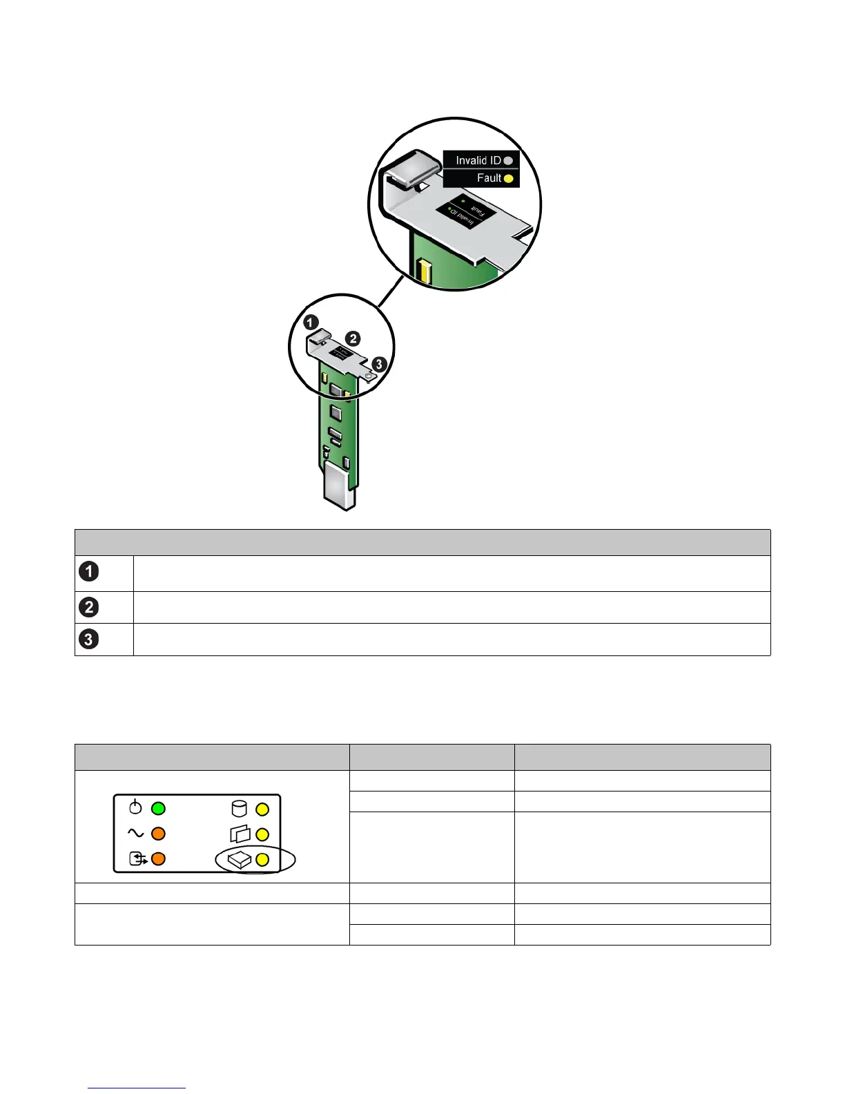
Figure 6-2: EIP Card and LEDs
The EIP card LEDs are described in Table 6-1. The LCD panel on the front panel (located behind the bezel) shows
additional information about EIP card failures.
Figure 6-2 Description
Mounting bracket. The bracket provides a way to hold an EIP card while protecting it from electrostatic
discharge or other damage.
LEDs. The LEDs show the EIP card status.
Thumbscrew. The thumbscrew secures the EIP card to the chassis.
Table 6-1: EIP Card LED Descriptions
EIP Card LED and Location Color Description
EIP card LED on array front
panel.
Off Normal operation.
Flashing yellow Card removed.
Yellow EIP card failure.
Invalid ID LED on EIP card. See Figure 6-2. Off Not used.
Fault LED on EIP card. See Figure 6-2. Off Normal operation.
Yellow Failure.