1. Align and place the display assembly on the computer chassis.
2. Replace the single (M2x4) screw and six (M2.5x5) screws that secure the display assembly to the computer chassis.
3. Connect the touch-screen cable to the connector on the system board.
4. Connect the display cable to the connector on the system board. Close the latch to secure the cable.
5. Replace the display cable bracket on the system board. Replace the single screw (M2x3) to secure the display bracket to the
system board.
6. Connect the two antenna cables to the WLAN module on the system board.
7. Replace the WLAN antenna cable bracket on the system board.
8. Replace the single screw (M2x3) that secures the WLAN antenna cable bracket to the system board.
1. Install the palmrest and keyboard assembly.
2. Follow the procedure in after working inside your computer.
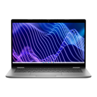
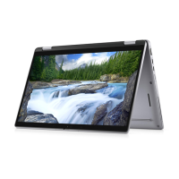
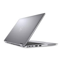
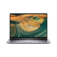
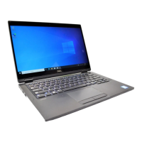
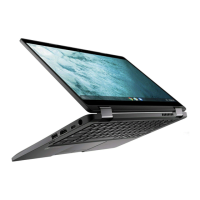
Touch-panel assembly (2-in-1)
Removing the touch-panel assembly (2-in-1)
1. Follow the procedure in before working inside your computer.
2. Remove the palmrest and keyboard assembly.
3. Remove the display assembly.
NOTE: The following touch-panel assembly removal procedure is applicable to Latitude 3140 2-in-1 only.
The following images indicate the location of the touch-panel assembly and provide a visual representation of the removal
procedure.
60
Removing and installing components
 Loading...