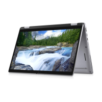
5. Adjust the display hinge caps to 90 degrees and the display hinges to 180 degrees so that the display assembly can lay flat on
the surface.
6. Lift and remove the touch-panel assembly from the display cover.
7. Gently flip over the display panel assembly and place it on a flat surface.
CAUTION:
The display cable is not long enough to completely flatten the panel. Technicians must move the
touch-panel assembly underneath the display hinges.
8. Peel off the mylar tape that secures the display cable on the rear of the display panel.
9. Peel off the rubber sticker from the display-cable connector.
10. Disconnect the display cable from the connector on the display panel.
11. Peel off the tape that secures the connector on the touch-control board.
12. Disconnect the display cable from the connector on the touch-control board.
13. Lift and remove the touch-panel assembly.
Installing the touch-panel assembly (2-in-1)
If you are replacing a component, remove the existing component before performing the installation procedure.
NOTE: The following touch-panel assembly installation procedure is applicable to Latitude 3140 2-in-1 only.
The following image indicates the location of the touch panel assembly and provides a visual representation of the installation
procedure.
Removing and installing components
63

 Loading...


