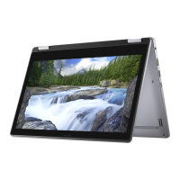
CAUTION: Hold the system rmly when the system is placed at this position.
8 Remove the 6 M2.5x2.5 screws [1] and lift the display assembly away from the computer [2].
CAUTION
: Hold the display assembly rmly when you place the display assembly at a 90 degree angle to the palm rest, to
avoid damaging the display assembly.
38 Removing and installing components

 Loading...


