i. card retention bracket
j. heat sink(s)/heat-sink blank(s)
k. processors(s)/processor blank(s)
CAUTION: To prevent damage to the processor pins when replacing a faulty system
board, ensure that you cover the processor socket with the processor protective cap.
l. memory modules and memory module blanks
m. network daughter card
Steps
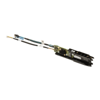
1. Disconnect the mini SAS cable from the system board.
2. Disconnect all other cables from the system board.
CAUTION: Take care not to damage the system identification button while removing the
system board from the chassis.
CAUTION: Do not lift the system board assembly by grasping a memory module, processor,
or other components.
3. Hold the system-board holder, lift the blue release pin, lift the system board and slide it toward the
front of the chassis.
Sliding the system board toward the front of the chassis disengages the connectors from the back of
the chassis slots.
4. Lift the system board out of the chassis.
117
 Loading...