4. Disconnect the microphone-module cable from the connector on the system board.
5. Disconnect the SIO-signal cable from the connector on the system board.
6. Disconnect the speaker cable from the connector on the system board.
7. Disconnect the audio-board cable from the connector on the system board.
8. Disconnect the SIO-power cable from the connector on the system board.
9. Disconnect the display cable from the connector on the system board.
10. Open the latch and disconnect the power-button board cable from the connector on the system board.
11. Disconnect the display back-light cable from the connector on the system board.
12. Remove the seven screws (M3x5) that secure the system board to the display-assembly base.
13. Lift and remove the system board from the display-assembly base.
Installing the system board
Prerequisites
If you are replacing a component, remove the existing component before performing the installation procedure.
About this task
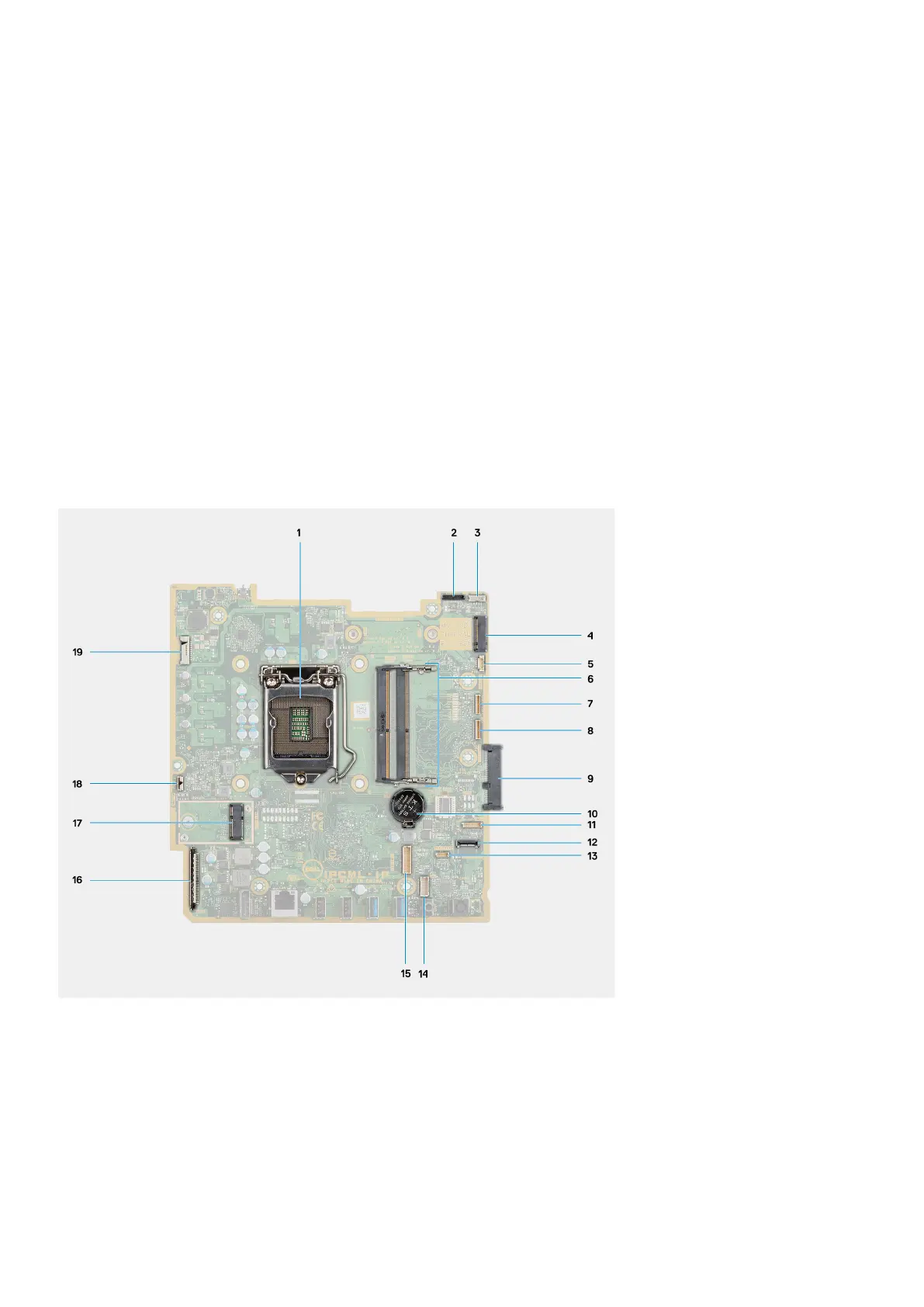
The following image indicates the connectors on your system board.
1. Processor 2. Camera cable connector
3. Touch-screen cable connector 4. M.2 2230/2280 solid-state drive/Intel Optane PCIe
connector
5. System-fan cable connector 6. Memory module
7. eSPI Debug Card cable connector 8. EC debug connector
9. Hard-drive connector 10. Coin-cell battery
11. Microphone-module cable connector 12. SIO-signal cable connector
13. Speaker cable connector 14. Audio-board cable connector
15. SIO-power cable connector 16. Display cable connector
Removing and installing components 55