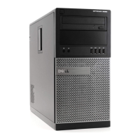
Steps
1. Insert the main-antenna into the ANT-W slot and auxiliary-antenna into the ANT-B slot.
NOTE: Applies if you are upgrading the system that did not have these optional modules.
2. Route the antennas using the routing guides and insert the antenna cables through the hole that is provided in the system
chassis.
3. Replace the two screws to secure the main and auxiliary antennas to the system chassis.
4. Connect the antenna cables to the WLAN card.
The following table provides the antenna-cable color scheme:
Table 3. Antenna-cable color scheme
Connectors on the wireless card Antenna-cable color
Main (white triangle) White
Auxiliary (black triangle) Black
Next steps
1. Install the side cover.
2. Follow the procedure in after working inside your computer.
System board
Removing the system board
Prerequisites
1. Follow the procedure in before working inside your computer.
NOTE:
Your computer’s Service Tag is stored in the system board. You must enter the Service Tag in the BIOS setup
program after you replace the system board.
Removing and installing components 73