4. Remove the eight (#6-32) screws that secure the system board to the chassis.
5. Remove the (M2x4) screw that secures the system board to the chassis.
6. Lift the system board at an angle and remove the system board off the chassis.
Installing the system board
Prerequisites
If you are replacing a component, remove the existing component before performing the installation procedure.
About this task
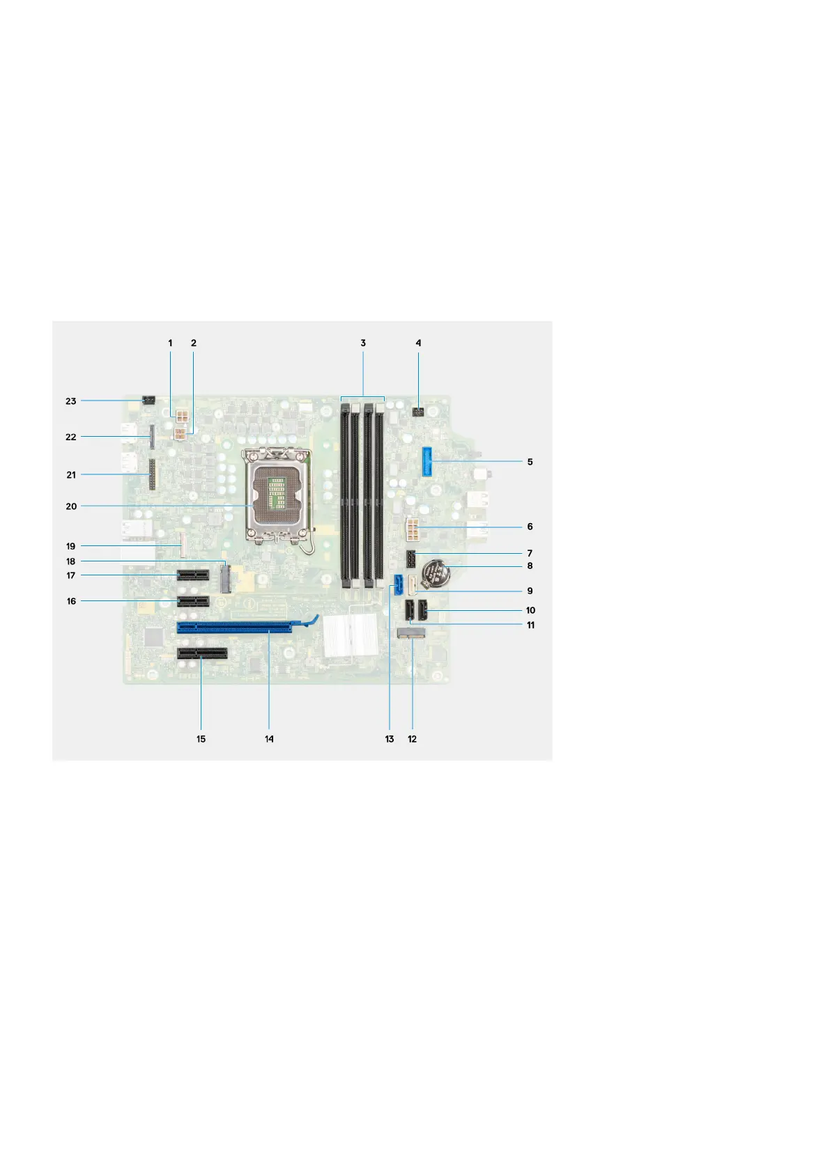
The following image indicates the connectors on your system board.
1. ATX CPU power connector
2. ATX CPU power connector
3. Memory module connectors
4. Power button connector
5. SD card reader connector
6. System power connector
7. SATA power cable connector
8. Coin-cell battery
9. SATA3 connector (white)
10. SATA 1connector (black)
11. SATA 2 connector (black)
12. M.2 WLAN connector
13. SATA0 connector (blue)
14. PCIe x16 (Slot2)
15. PCIe x4 (Slot4)
16. PCIe x1 (Slot1/2)
17. PCIe x1 (Slot1/2)
78
Removing and installing components