NOTE: Replacing the system board removes any changes that you have made to the BIOS using the BIOS setup
program. You must make the appropriate changes again after you replace the system board.
NOTE: Before disconnecting the cables from the system board, note the location of the connectors so that you can
reconnect the cables correctly after you replace the system board.
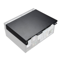
2. Remove the side cover.
3. Remove the front bezel.
4. Remove the fan duct.
5. Remove the memory module.
6. Remove the WLAN.
7. Remove the M.2 2230 SSD/M.2 2280 SSD.
8. Remove the coin-cell battery.
9. Remove the graphics card.
10. Remove the speaker.
11. Remove the intrusion switch.
12. Remove the processor fan and heat-sink assembly.
13. Remove the processor.
About this task
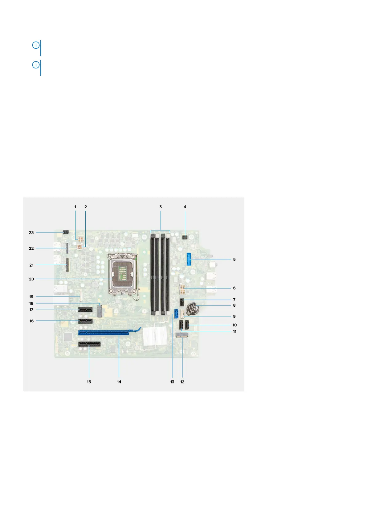
The following image indicates the connectors on your system board.
1. ATX CPU power connector
2. ATX CPU power connector
3. Memory module connectors
4. Power button connector
5. SD card reader connector
6. System power connector
7. SATA power cable connector
8. Coin-cell battery
9. SATA3 connector (white)
10. SATA 1connector (black)
74
Removing and installing components